OptiFiber® Pro OTDR Family


Product Highlights
Makes novices into experts and experts faster
- Multiple wavelengths (850, 1300, 1310,1490, 1550 and 1625 nm) support LAN, datacenters, PON, FTTx and outside plant applications.
- Automated setup senses fiber characteristics and sets measurement parameters
- Manual Expert mode allows simple adjustments to automated settings for detailed testing.
- EventMap automatically identifies events including connectors, splices, bends, and splitters
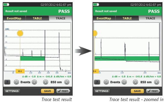
- Gesture-based interface allows fast, in-depth trace analysis
- SmartLoop™ OTDR technology tests two fibers in a single test eliminating the need to travel to the far end of the connection to perform tests.
- Instantaneous on-board bi-directional averaging results included as standard
- Integrates with LinkWare™ Live to manage jobs and testers from any smart device.
- Future-ready VersivTM design supports copper certification to Category 8, fiber loss and inspection.
Overview
Designed for Enterprise, Datacenter, Outside Plant and PON Fiber
As fiber networks evolve, the need to test in more locations has increased. OTDRs are now needed for:
FTTx
Enterprise
OSP
PON
POLAN
Many OTDRs designed for fiber troubleshooting are designed for carrier and contain cumbersome and complicated features. The OptiFiber Pro OTDR family is the first class of OTDRs that is built with features and usability for both the enterprise network engineers, and cable installers working in both enterprise and OSP environments.
Features
Smartphone User Interface
Most OTDRs are designed for a myriad of applications, causing the user interface to be difficult to navigate and interpret. OptiFiber Pro combines the latest “gesture-based” interface technology with a capacitive touchscreen to deliver the most innovative and user-friendly OTDR.
Advantages:
- Single-touch tap and swipe control for selecting and scrolling menu items
- Multi-touch pinch to zoom for easy magnification control on a graphical fiber trace
- Task-focused design to reduce back and forth navigation through screens
- Capacitive touchscreen eliminates the need to recalibrate unlike legacy touchscreens
- Context sensitive on-screen help that gives users additional details or problem resolution suggestions
At Home in the Datacenter
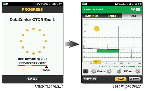
Driven by server virtualization and multi-gigabit links between servers, networks and storage, the datacenter architecture employs more patch cords and dense topology connectors, rendering carrier-class OTDRs with long dead zones ineffective. OptiFiber Pro not only makes fiber deployment in datacenters possible, but provides the highest level of accuracy for quick problem resolution.
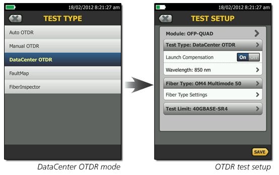
With a simple one-touch selection, users enter DataCenter OTDR mode - without setup time for fine-tuning as needed in legacy OTDRs. DataCenter OTDR mode automatically detects OTDR parameters - end-detection algorithms, pulse widths, etc - without getting confused by the short links or number of connectors.
Advantages:
- Ultra-short event and attenuation dead-zones precisely locates events and faults on fiber links in the Enterprise
- DataCenter OTDR™ mode automatically sets the configuration to quickly test datacenter fiber
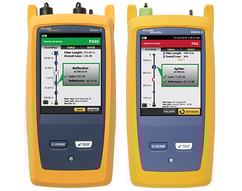
- The EventMap feature depicts fiber events in a way that requires no trace analysis expertise
Unique Certification with Flexibility and Efficiency
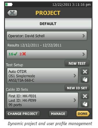
An important aspect in maximizing an OTDR’s value is to properly plan its day-to-day usage. With built-in project management, OptiFiber Pro allows a project manager to define each user’s role, settings and the associated tasks to be performed – transforming the OTDR into an all-in-one fiber testing tool complete with planning, inspection, certification and reporting.
OptiFiber Pro enhances job efficiency by allowing the workflow planner to create and manage operator and job profiles per project - defined jobs or sets of cable IDs can be assigned to specific operators. The progress and status of each project can also be easily monitored.
Advantages:
- Full OTDR capability that certifies fiber performance based on job assignment for each operator
- Powerful project management facilitates OTDR sharing with clear job assignment for each operator
- Easy monitoring of job progress with pass/fail results
- On-screen report generation and upload to LinkWare™ application
Other Key Features
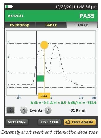
Extremely short event and attenuation dead zone for the Enterprise
The OptiFiber Pro leverages the most sophisticated optical technology to provide the shortest event dead zone (0.5 m typical for MM) and attenuation dead zone (2.2 m typical for MM and 3.6 m typical for SM) of any OTDR. This technological advancement allows OptiFiber Pro to detect and measure closely spaced faults where no other OTDR can in today’s connector-rich datacenter and storage area environments.
Two second trace per wavelength
Another breakthrough with OptiFiber Pro is the data acquisition speed. While in Quick Test mode, a complete set of data is acquired in as little as two seconds per wavelength. OptiFiber Pro then analyzes the data and displays it as an EventMap, Table or Trace. The end result is less time spent testing and more time performing other tasks.
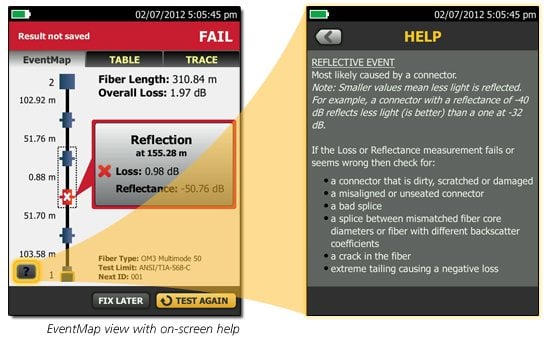
On-screen help – corrective action
On-screen “help” suggests corrective action(s) for resolving fiber problems during each testing step. The “help” offered is context sensitive which allows users to quickly pinpoint possible resolutions. An easy-to-read, gray icon in the bottom, left-hand corner shows detailed corrective action recommendations.
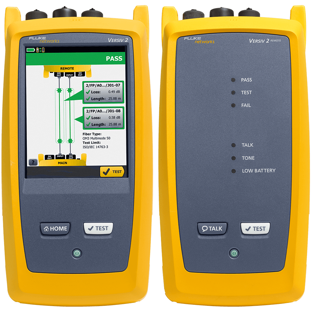
SmartLoop OTDR
SmartLoop OTDR enables automated testing and analysis of two fibers in a single test while meeting standard requirements. This patented process automatically separates the two fibers for individual pass/fail analysis, display, and reporting. Not only does this cut the testing time by at least half, it also enables instant bi-directional averaged test results without moving the OTDR to the far end. In addition to getting the job done quicker, SmartLoop OTDR further enhances the ease and speed of testing in environments where the far end is difficult of even dangerous to reach because the OTDR never has to be moved to the far end. In addition to getting the job done quicker, SmartLoop meets the standard's requirements of leaving the launch and tail fibers in their initial locations during both bi-directional tests.
Test it right and test it fast with SmartLoop - included for free in all OptiFiber Pro modules.
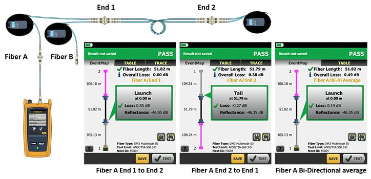
OptiFiber Pro's SmartLoop technology test two fibers in one tests while providing individual pass, fail and bi-directionally averaged results for each fiber link.
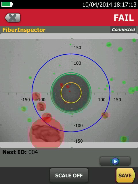
Fiber Endface Inspection and Certification
OptiFiber Pro incorporates the FiberInspector Pro video inspection system which enables you to quickly inspect and certify fiber end-faces inside ports or patch cords. It’s 1-second automated PASS/FAIL certification, per IEC 61300-3-35, eliminates human subjectivity and enables anyone to become a fiber inspection expert. Results can be saved in the certification report alongside OptiFiber Pro's OTDR results.
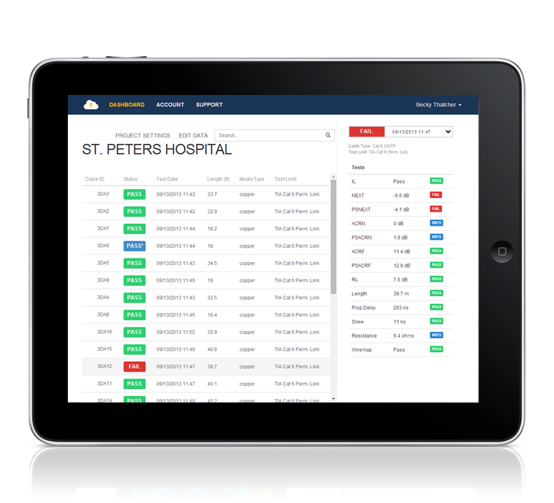
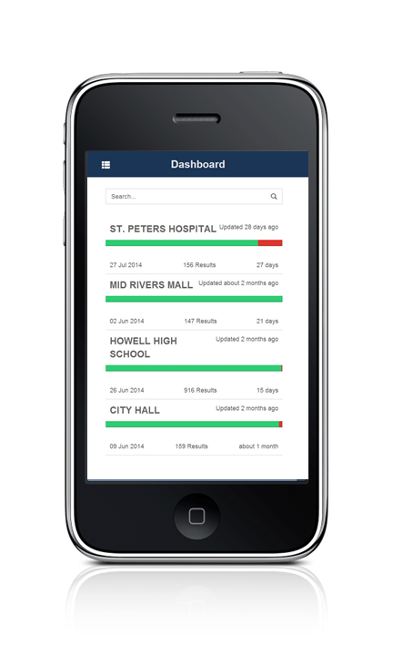
LinkWare™ Live Test Results Management Service
LinkWare Live is a cloud-based service that lets you manage certification jobs anytime, anywhere, with anyone on any device. With LinkWare Live, you can
- Keep track of every test on every job. Get an overview of every project from any smart device. Drill down to each individual test. Instantly receive notification of incorrect test setting or cable IDs.
- Get it right the first time. Define cable IDs and test settings from your PC or tablet. Then send them to the testers or Brother printers at the jobsite for mistake-free testing and labeling.
- Keep your testers up to date. Standards can change without notice, and an out-of-date test report can mean hours of re-testing. LinkWare Live automatically ensures your testers are running the latest.
- Stop wasting time and gas driving testers back to the office. Integrated Wi-Fi allows you to upload your test results straight from the job site to LinkWare Live. Then download them automatically to the right job for fast report generation with LinkWare PC.
- Avoid Project Delays. Track the last used location and monitor the status of all testers to ensure they are always calibrated and running the latest firmware*
- Supports all Versiv models: DSX CableAnalyzer Series, CertiFiber Pro, OptiFiber Pro, and the FI-7000.
*See supported countries.
Comparing the OptiFiber Pro and OptiFiber Pro HDR OTDRs
| OptiFiber Pro Series OTDRs | ||
| OptiFiber Pro | OptiFiber Pro HDR | |
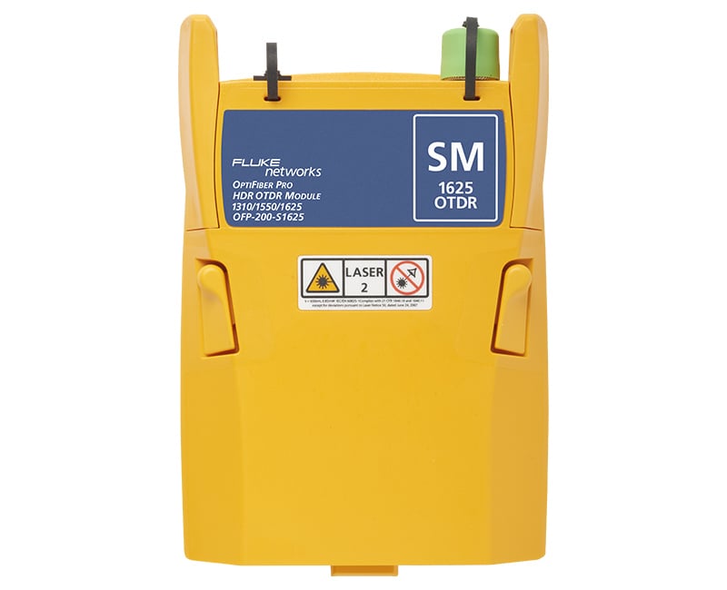
| Models in Series | OFP2-100-M (850, 1300 nm) OFP2-100-S (1310, 1550 nm) OFP2-100-Q (850, 1300, 1310, 1550 nm) | OFP2-200-S (1310, 1550 nm) OFP2-200-S1490 (1310, 1490, 1550 nm) OFP2-200-S1625 (1310, 1550, 1625 nm) |
| Application | Enterprise, Datacenter, Campus | FTTx, Outside Plant, PON, POLAN, Access |
| Wavelengths | 850 nm 1300 nm 1310 nm 1550 nm | 1310 nm 1490 nm 1550 nm 1625 nm |
| Compatible fiber types | 50/125 µm, 62.5 µm, Singlemode | Singlemode |
| OTDR Port Connector | Cleanable UPC ferrule with removable SC adapter | Cleanable APC ferrule with removable SC adapter |
| Supplied Test Cords | Launch Fibers for testing LC systems | 2m TRC for testing SCAPC systems |
| OTDR types | Auto, Datacenter, Manual | Auto, Auto PON, Manual, Manual PON |
| Event Dead Zone | 850 nm: 0.5 m (typical), 1300 nm: 0.7 m (typical), 1310 nm: 0.6 m (typical), 1550 nm: 0.6 m (typical) | 1310 nm: 0.7 m (typical), 1490 nm: 0.7 m (typical), 1550 nm: 0.7 m (typical), 1625 nm: 0.7 m (typical) |
| Attenuation Dead Zone | 850 nm: 2.5 m (typical), 1300 nm: 4.5 m (typical), 1310 nm: 3.6 m (typical), 1550 nm: 3.7 m (typical) | 1310 nm: 4 m (typical), 1490 nm: 4 m (typical), 1550 nm: 4 m (typical), 1625 nm: 4 m (typical) |
| PON Dead Zone | N/A | 30 m (typical) |
| Dynamic Range | 850 nm: 28 dB (typical) 1300 nm: 30 dB (typical) 1310 nm: 32 dB (typical) 1550 nm: 30 dB (typical) | 1310 nm: 42 dB (typical) 1490 nm: 41 dB (typical) 1550 nm: 41 dB (typical) 1625 nm: 40 dB (typical) |
| Reflectance range | 850 nm: -14 dB to -57 dB (typical), 1300 nm: -14 dB to -62 dB (typical), 1310 nm: -14 dB to -65 dB (typical), 1550 nm: -14 dB to -65 dB (typical) | 1310 nm: -14 to -70 dB (typical), 1490 nm: -14 dB to 70 dB (typical), 1550 nm: -14 dB to -70 dB (typical), 1625 nm: -14 dB to -70 dB (typical) |
| Sampling Resolution | Up to 64,000 | Up to 129,000 |
| Expert Manual Mode | Yes | Yes |
| SmartLoop with on-board | Yes | Yes |
| Macrobend detection | Yes | Yes |
| Span Support | Coming early 2019 | |
| Event editing and additions | Coming early 2019 | |
| VFL | Yes | Yes |
New High Dynamic Range and New Wavelengths
OptiFiber Pro HDR has a dynamic range up to 42 dB and adds new wavelengths for outside plant/FTTx/PON testing requirements. Three wavelength combinations are available depending upon your requirements.
- 1310/1550 nm
- 1310/1490/1550 nm
- 1310/1550/1625 nm
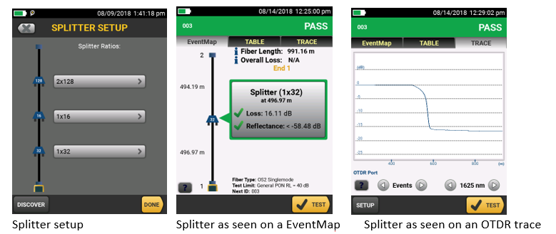
Splitter detection
OptiFiber Pro HDR is optimized for FTTx/PON testing through splitters. 1x16 and 1x32 are most commonly found today but OptiFiber Pro HDR is future proofed for testing even nx128 splitters. With its Discover function, you can automatically locate splitters and their ratios. Up to 3 cascaded splitters can be configured in the setup.
OptiFiber Pro HDR provides two PON test suites: Auto PON OTDR and Manual PON OTDR.
- Auto PON OTDR -The tester automatically selects settings that give you the best view of the events on OSP (outside plant) cabling. The tester automatically uses the DISCOVER function to identify splitters. This mode is the easiest to use and is the best choice for most applications.
- Manual PON OTDR - This mode lets you select settings to control the parameters of the trace. You can also enter the ratios of splitters that you know are on the link, or use the DISCOVER function to locate splitters and identify their ratios.
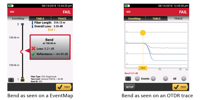
Macrobend detection
A bend in a fiber cable, if pulled around a sharp corner for instance, allows light to escape from the fiber’s core. This Macrobend may be a risk for mechanical or optical failure. OptiFiber Pro automatically identifies bends and their location by comparing the loss of an event at multiple wavelengths.
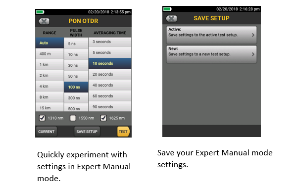
Expert Manual Mode
Starting with settings from Auto OTDR mode, Expert Manual mode allows user to quickly experiment with settings to uncover details of interest.
- Easy to use manual settings – simplifies experimentation via on the trace screen
- Change the range, pulse width, averaging time, and wavelength
- Try the setting out before saving
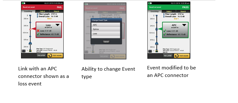
Edit Events
When testing or certifying fiber runs, you want the test results to reflect the links as-built. Sometimes an OTDR can misidentify or not find all the actual events within a link. The Edit Event function provides users with the ability to edit, add or remove events including:
- Changing an event to: an APC connector, a splice or a loss event
- Allows the insertion of a splice, such as a 0dB event, at a given location when the splice is hidden due to noise or the splice loss is lower than the minimum detection threshold
- Once the event is modified, the PASS/FAIL status of the link will be updated to reflect the modification
- APC connectors may be identified as a splice instead of as an APC connector because they are non-reflective like a splice. This can cause problems since the loss budget for a splice is less than that of an APC connector. Allowing you to edit the splice and change it to an APC connector allows the loss budget to be calculated correctly for the link.
- Edited events are marked in reports so they can easily be identified as having been edited
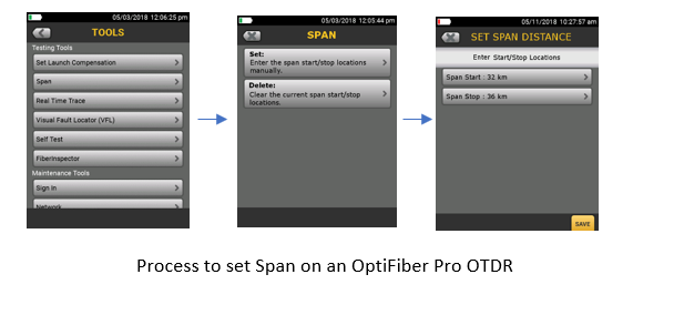
Span a portion of a link
When testing a fiber run (particularly in outside plant applications) you may only be interested in a small section of the cabling. For example, if you are repairing a short section of a longer trunk, span allows you to define the start and end of your short section so that the OTDR analyzes only the section that you repaired.
- Provides the ability to perform PASS/FAIL analysis on a section of fiber under test
- PASS/FAIL analysis is only generated for events located with the span distance
- Events outside the span range are evaluated as info only
LinkWare PC
LinkWare™ PC management software
Leveraging the popular and multi-featured LinkWare cable test management software application, OptiFiber Pro users can easily access the hassle-free project management, report generation, and software upgrade capabilities to manage workflow and consolidate test results.
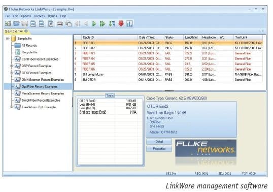
Stackable results & batch process of traces via LinkWare PC
LinkWare PC allows for the batch processing of traces so you can quickly and easily make edits to many traces at one time. Stacking traces allows you to visually identify differences between identical fibers, such as strands within a trunk. LinkWare PC does this by allowing multiple traces to be overlaid and stacked with separation so that differences in the graph can easily be spotted.
Unique Certification with Flexibility and Efficiency
An important aspect in maximizing an OTDR’s value is to properly plan its day-to-day usage. With ProjX management system, OptiFiber Pro allows a project manager to define each user’s role, settings and the associated tasks to be performed – transforming the OTDR into an all-in-one fiber testing tool complete with planning, inspection, certification and reporting.
Advantages:
- Powerful ProjX management system facilitates OTDR sharing with clear job assignment for each operator
- Easy monitoring of job progress with pass/fail or document only results
- Built-in Visual Fault Locator (VFL) to facilitate troubleshooting
- On-screen report generation and upload to LinkWare™ application
- Integrated Wi-Fi allows you to easily upload results to LinkWare™ Live
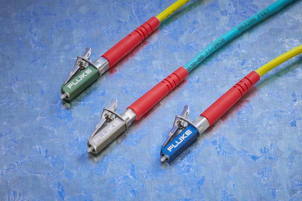
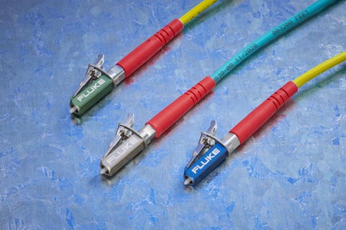
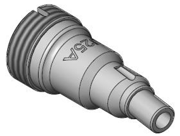
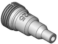
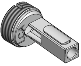
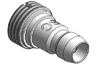
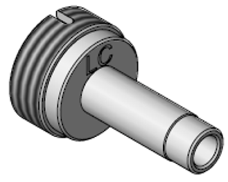
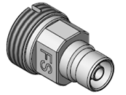
Rugged Metal LC Connectors
Fluke Networks Test Reference Cords and Launch Fibers with LC connectors feature our unique metal latch design. Traditional LC connectors use a single-piece plastic design that flexes the latching mechanism each time the connector is inserted and removed and eventually breaks, making them unsuitable for repeated use in testing. The Fluke Networks Metal LC latching system uses a multi-piece metal design with a spring located between the latch and connector body. Since this latch is not part of the body and does not flex, the life of the latching mechanism is greatly improved, thereby extending the life of the LC connector and therefore the TRC’s and launch cords.
The Metal LC connector is compliant with IEC 61754-20 and TIA-604-10B intermateability standards. That latch has also been tested for up to 10,000 insertions with no degradation in performance and passes all Telecordia GR-326-CORE durability tests including thermal, humidity, vibration, flex, impact, and salt spray. While the connector itself is the most rugged available, the glass fiber endface is still susceptible to damage, so it’s important to inspect the endface to make sure it’s contaminant-free and to properly clean it if necessary.
Models & Accessories
Models
OFP2-100-M-NW GOLD
OFP2-100-M-NW Gold Support
Same configuration as the OFP2-100-M with integrated Wi-Fi disabled.
Learn more about Fluke Premium Care – Gold
GLD-OFP-100-M
1 year of Gold Support for OFP2-100-M, OFP2-100-M-NW, OFP-100-M-W or OFP-100-M
GLD3-OFP-100-M
3 years of Gold Support for for OFP2-100-M, OFP2-100-M-NW, OFP-100-M-W or OFP-100-M
OFP2-100-S-NW GOLD
OFP2-100-S-NW Gold Support
Same configuration as the OFP2-100-S with integrated Wi-Fi disabled.
Learn more about Fluke Premium Care – Gold
GLD-OFP-100-S
1 year of Gold Support for OFP2-100-S, OFP2-100-S-NW, OFP-100-S-W or OFP-100-S
GLD3-OFP-100-S
3 years of Gold Support for OFP2-100-S, OFP2-100-S-NW, OFP-100-S-W or OFP-100-S
OFP2-100-Q-NW GOLD
OFP2-100-Q-NW Gold Support
Same configuration as the OFP2-100-Q with integrated Wi-Fi disabled.
Learn more about Fluke Premium Care – Gold
GLD-OFP-100-Q
1 year of Gold Support for OFP2-100-Q, OFP2-100-Q-NW, OFP-100-Q-W or OFP-100-Q
GLD3-OFP-100-Q
3 years of Gold Support for OFP2-100-Q, OFP2-100-Q-NW, OFP-100-Q-W or OFP-100-Q
OFP-MM GOLD
OFP-MM Gold Support
OptiFiber Pro Multimode OTDR module.See Photo
Learn more about Fluke Premium Care – Gold
GLD-OFP-MOD-M
1 year of Gold Support coverage for OptiFiber Pro Multimode module - Model: OFP-MM
GLD3-OFP-MOD-M
3 years of Gold Support coverage for OptiFiber Pro Multimode module - Model: OFP-MM
OFP-SM GOLD
OFP-SM Gold Support
OptiFiber Pro Singlemode OTDR module See Photo
Learn more about Fluke Premium Care – Gold
GLD-OFP-MOD-S
1 year of Gold Support coverage for OptiFiber Pro Singlemode module - Model: OFP-SM
GLD3-OFP-MOD-S
3 years of Gold Support coverage for OptiFiber Pro Singlemode module - Model: OFP-SM
OFP-QUAD GOLD
OFP-QUAD Gold Support
OptiFiber Pro Quad OTDR module See Photo
Learn more about Fluke Premium Care – Gold
GLD-OFP-MOD-Q
1 year of Gold Support coverage for OptiFiber Pro Quad Module
GLD3-OFP-MOD-Q
3 years of Gold Support coverage for OptiFiber Pro Quad Module
OFP-Q-ADD GOLD
OFP-Q-ADD Gold Support
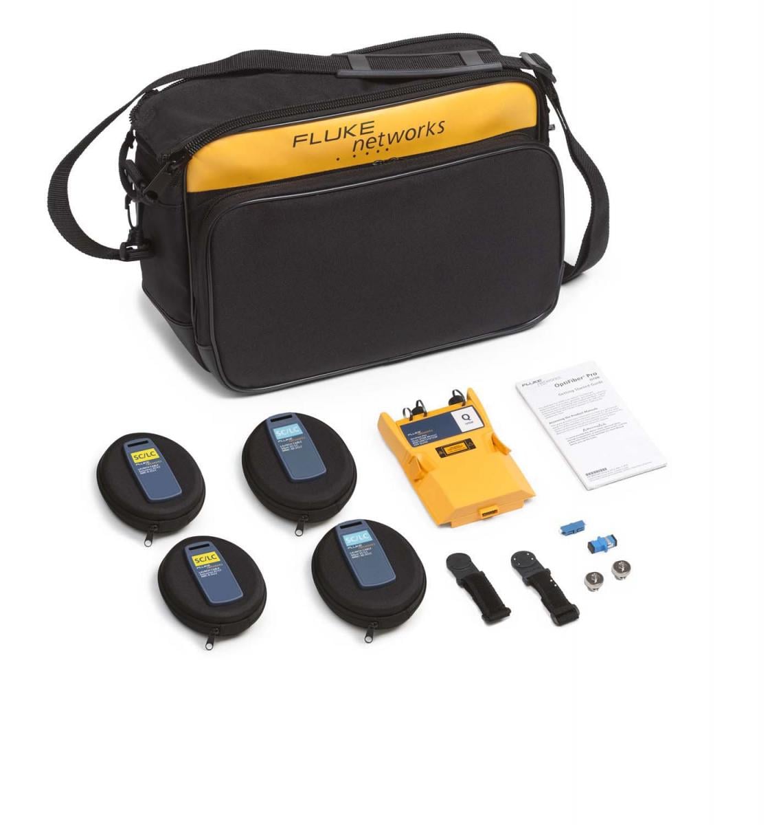
OptiFiber Pro Add on Kit - includes OptiFiber Pro Quad OTDR Module, (2) SC/LC Multimode Launch Cables—50 µm, (2) SC/LC Singlemode Launch Cable—9 µm, (2) OTDR source port interchangeable LC adapters, SC/SC Simplex Adaptor, LC/LC Simplex Adaptor, (2) Launch Fiber Hanging straps and magnets, Carry Case, Statement of Calibration and Getting Started Guide.See Photo
Learn more about Fluke Premium Care – Gold
GLD-OFP-Q-ADD
1 year of Gold Support coverage for OFP-Q-ADD
GLD3-OFP-Q-ADD
3 years of Gold Support coverage for OFP-Q-ADD
OptiFiber Pro Models
OptiFiber Pro Models
OFP2-100-M GOLD
OFP2-100-M Gold Support
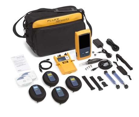
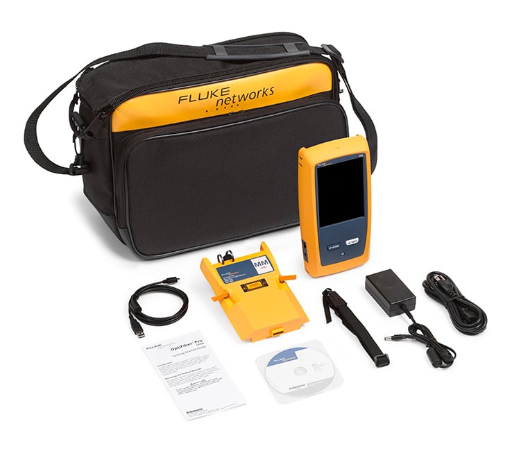
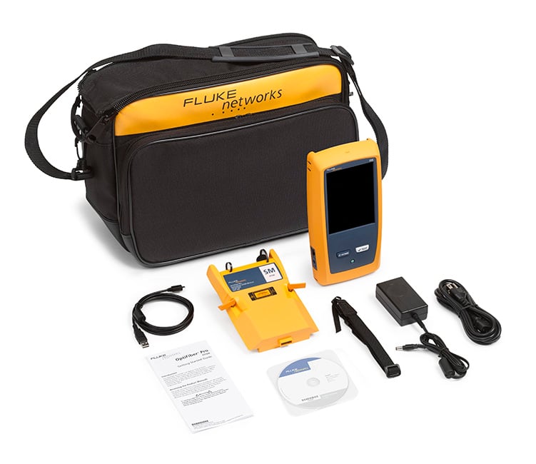
OptiFiber Pro Multimode OTDR kit.See Photo
Learn more about Fluke Premium Care – Gold
GLD-OFP-100-M
1 year of Gold Support for OFP2-100-M, OFP2-100-M-NW, OFP-100-M-W or OFP-100-M
GLD3-OFP-100-M
3 years of Gold Support for for OFP2-100-M, OFP2-100-M-NW, OFP-100-M-W or OFP-100-M
OFP2-100-MI GOLD
OFP2-100-MI Gold Support
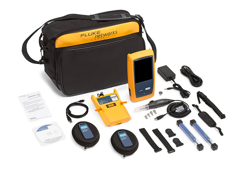
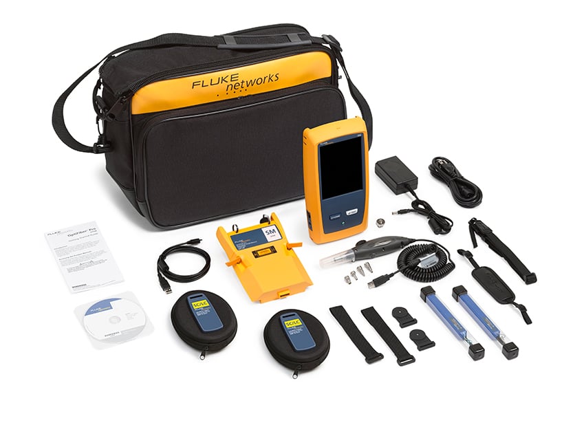
OptiFiber Pro Multimode OTDR V2 kit with inspection kit with Wi-Fi. This kit includes (1) Versiv 2 Mainframe, (1) OptiFiber Pro Multimode OTDR module, Shoulder Strap, USB Interface Cable, Carry Case, AC Charger, (2) Quick Clean Cleaners (1.25/2.50 mm), (2) SC/LC Multimode Launch Cables—50 µm, (1) OTDR source port interchangeable LC adapters, USB Fiber Inspection Video Probe with 4 Tips, SC/SC Simplex Adaptor, (2) Launch Fiber Hanging straps and magnets, Integrated Wi-Fi, Statement of Calibration and Getting Started Guides.See Photo
Learn more about Fluke Premium Care – Gold
GLD-OFP-100-MI
1 year of Gold Support for OFP2-100-MI, OFP-100-MI-W or OFP-100-MI
GLD3-OFP-100-MI
3 years of Gold Support for OFP2-100-MI, OFP-100-MI-W or OFP-100-MI
OFP2-100-S GOLD
OFP2-100-S Gold Support
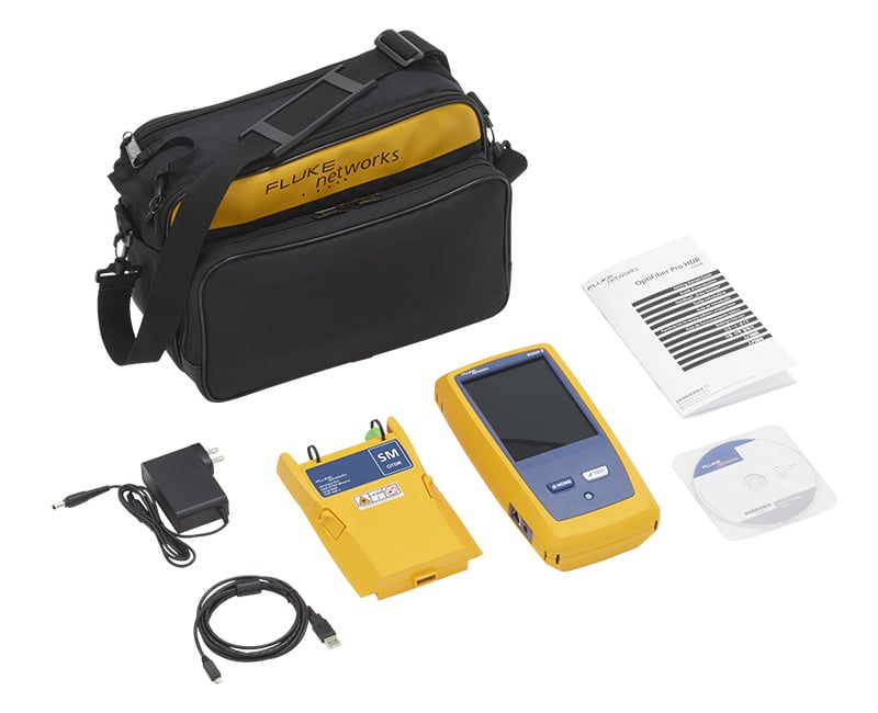
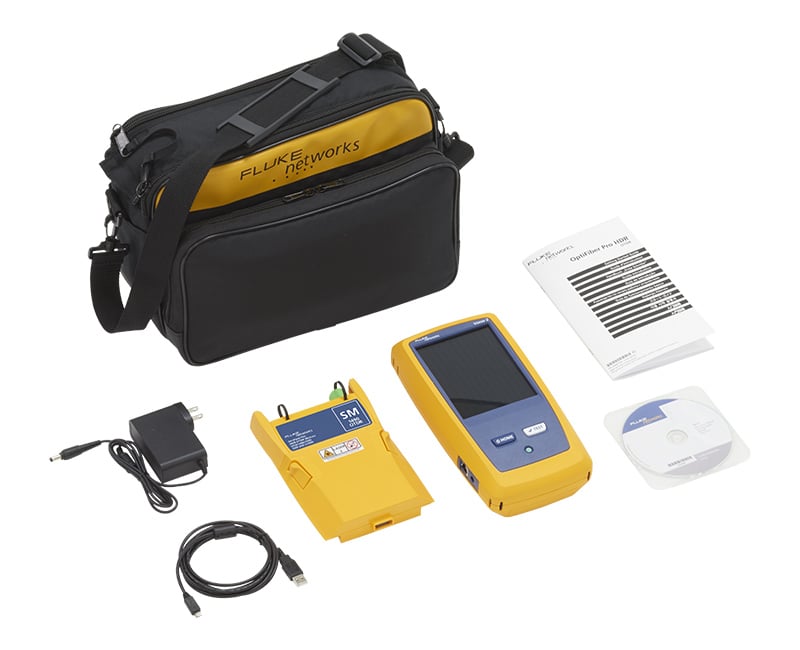
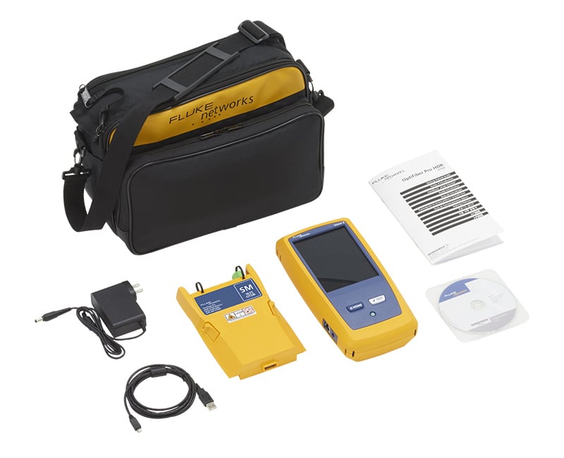
OptiFiber Pro Singlemode OTDR V2 kit with Wi-Fi. This kit includes (1) Versiv 2 Mainframe, (1) OptiFiber Pro Singlemode OTDR module, Shoulder Strap, USB Interface Cable, Carry Case, AC Charger, Integrated Wi-Fi, Statement of Calibration and Getting Started Guides.See Photo
Learn more about Fluke Premium Care – Gold
GLD-OFP-100-S
1 year of Gold Support for OFP2-100-S, OFP2-100-S-NW, OFP-100-S-W or OFP-100-S
GLD3-OFP-100-S
3 years of Gold Support for OFP2-100-S, OFP2-100-S-NW, OFP-100-S-W or OFP-100-S
OFP2-100-SI GOLD
OFP2-100-SI Gold Support
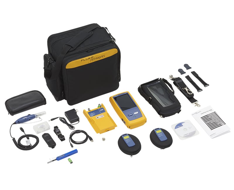
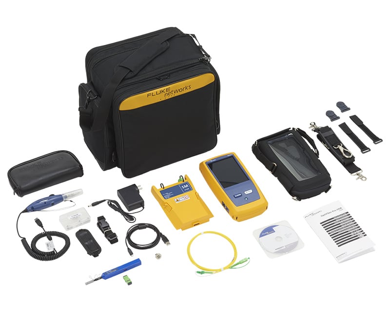
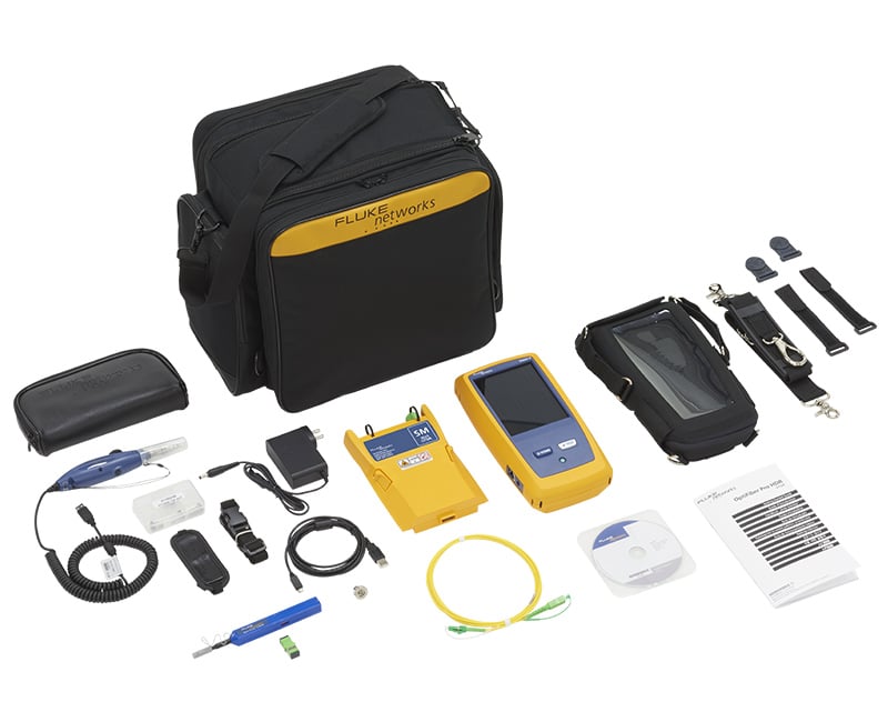
OptiFiber Pro Singlemode OTDR V2 kit with inspection and Wi-Fi. This kit includes (1) Versiv 2 Mainframe, (1) OptiFiber Pro Singlemode OTDR module, Shoulder Strap, USB Interface Cable, Carry Case, AC Charger, (2) Quick Clean Cleaners (1.25/2.50 mm), (2) SC/LC Singlemode Launch Cables—9 µm, (1) OTDR source port interchangeable LC adapters, USB Fiber Inspection Video Probe with 4 Tips, SC/SC Simplex Adaptor, (2) Launch Fiber Hanging straps and magnets, Integrated Wi-Fi, Statement of Calibration and Getting Started Guides.See Photo
Learn more about Fluke Premium Care – Gold
GLD-OFP-100-SI
1 year of Gold Support for OFP2-100-SI, OFP-100-SI-W or OFP-100-SI
GLD3-OFP-100-SI
3 year of Gold Support for OFP2-100-SI, OFP-100-SI-W or OFP-100-SI
OFP2-100-Q GOLD
OFP2-100-Q Gold Support
OptiFiber Pro Quad OTDR V2 kit with Wi-Fi. This kit includes (1) Versiv 2 Mainframe, (1) OptiFiber Pro Quad OTDR module, Shoulder Strap, Carry Case, USB Interface Cable, Carry Case, AC Charger, Integrated Wi-Fi, Statement of Calibration and Getting Started Guides.See Photo
Learn more about Fluke Premium Care – Gold
GLD-OFP-100-Q
1 year of Gold Support for OFP2-100-Q, OFP2-100-Q-NW, OFP-100-Q-W or OFP-100-Q
GLD3-OFP-100-Q
3 years of Gold Support for OFP2-100-Q, OFP2-100-Q-NW, OFP-100-Q-W or OFP-100-Q
OFP2-100-Q/GLD GOLD
OFP2-100-Q/GLD Gold Support
OFP2-100-Q with 1 year of Gold Support (available in the United States and Europe. Europe order: OFP2-100Q/GLD INT).
Learn more about Fluke Premium Care – Gold
OFP2-100-QI GOLD
OFP2-100-QI Gold Support
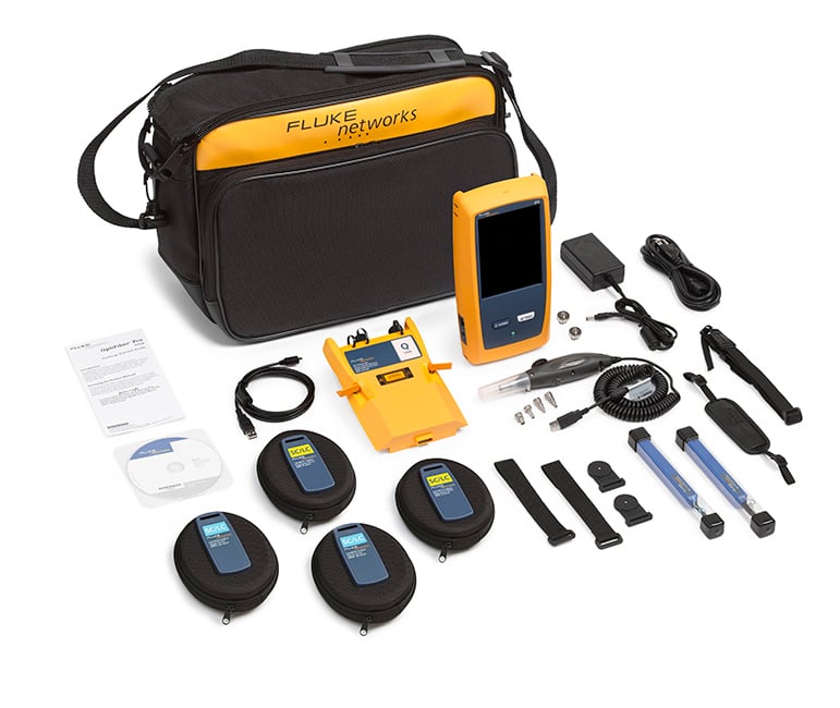
OptiFiber Pro Quad OTDR V2 kit with inspection and Wi-Fi. This kit includes (1) Versiv 2 Mainframe, (1) OptiFiber Pro Quad OTDR module, Shoulder Strap, Carry Case, USB Interface Cable, AC Charger, (2) Quick Clean Cleaners (1.25/2.50 mm), (2) SC/LC Multimode Launch Cables—50 µm, (2) SC/LC Singlemode Launch Cables—9 µm, (2) OTDR source port interchangeable LC adapters, USB Fiber Inspection Video Probe with 4 Tips, SC/SC Simplex Adaptor, (2) Launch Fiber Hanging straps and magnets, Integrated Wi-Fi, Statement of Calibration and Getting Started Guides.See Photo
Learn more about Fluke Premium Care – Gold
GLD-OFP-100-QI
1 year of Gold Support for OFP2-100-QI, OFP-100-QI-W or OFP-100-Q
GLD3-OFP-100-QI
3 years of Gold Support for OFP2-100-QI, OFP-100-QI-W or OFP-100-Q
OFP2-100-QI/GLD GOLD
OFP2-100-QI/GLD Gold Support
OFP2-100-QI with 1 year of Gold Support (available in the United States and Europe. Europe order: OFP2-100QI/GLD INT).
Learn more about Fluke Premium Care – Gold
OFP2-CFP-QI GOLD
OFP2-CFP-QI Gold Support
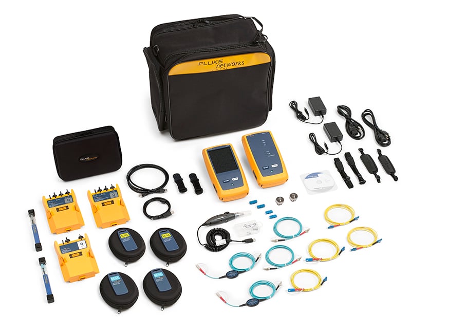
OptiFiber Pro Quad OTDR and CertiFiber Pro Quad V2 kit with inspection and Wi-Fi. This kit includes (1) Versiv 2 Mainframe & Remote, (1) OptiFiber Pro Quad OTDR module, (2) CertiFiber Pro Quad OLTS modules, (2) HandStraps, (2) Shoulder Straps, USB Interface Cable, Carry Case, (2) AC Chargers, (2) Quick Clean Cleaners (1.25/2.50 mm), (2) SC/LC Multimode Launch Cables—50 µm, (2) SC/LC Singlemode Launch Cables—9 µm, (2) OTDR source port interchangeable LC adapters, USB Fiber Inspection Video Probe with 4 Tips, SC/SC Simplex Adaptor, (2) LC/LC Simplex Adaptor, SC/LC SM TRC Kit 9 µm, SC/LC EFC TRC Kit 50 µm, Carry Case, (2) Launch Fiber Hanging straps and magnets, Integrated Wi-Fi, Statement of Calibration and Getting Started Guides.See Photo
Learn more about Fluke Premium Care – Gold
GLD-OFP-CFP-QI
1 year of Gold Support coverage for OFP2-CFP-QI or OFP-CFP-QI
GLD3-OFP-CFP-QI
3 years of Gold Support coverage for OFP2-CFP-QI or OFP-CFP-QI
OFP2-CFP-QI-NW
OFP2-CFP-QI-NW
Same configuration as the OFP2-CFP-QI-NW with integrated Wi-Fi disabled.
Learn more about Fluke Premium Care – Gold
OFP2-200-S
OFP2-200-S
OFP2-200-S-NW
OFP2-200-S-NW
OFP2-200-Si
OFP2-200-Si
OFP2-200-Si/GLD GOLD
OFP2-200-Si/GLD Gold Support
OFP2-200-S1490
OFP2-200-S1490
OFP2-200-S1490-NW
OFP2-200-S1490-NW
OFP2-200-Si1490
OFP2-200-Si1490
OFP2-200-S1625
OFP2-200-S1625
OFP2-200-S1625-NW
OFP2-200-S1625-NW
OFP2-200-Si1625
OFP2-200-Si1625
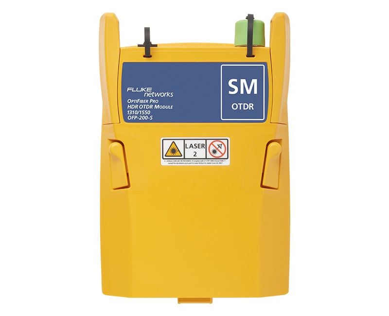
OFP-200-S-MOD
OFP-200-S-MOD
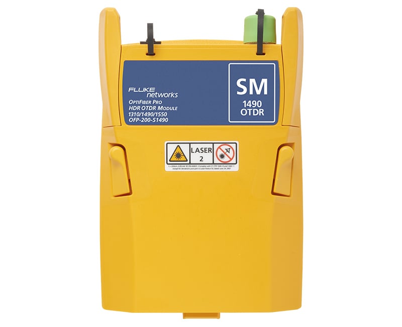
OFP-200-S1490-MOD
OFP-200-S1490-MOD
OFP-200-S1625-MOD
OFP-200-S1625-MOD
DSX2-8000OI GOLD
DSX2-8000OI Gold Support
Versiv Mainframe & Remote, (2) DSX-8000 CableAnalyzer Modules, Set of Cat 8/Class I Permanent Link Adapters, Set of Cat 8/Class I Channel Adapters, (2) Headsets, (2) HandStrap, (2) Shoulder Straps, Carry Case, USB Interface Cable, (2) AC Chargers, (2) Universal Couplers, (2) AxTalk Terminators, OptiFiber Pro Quad OTDR Module, (3) SC/LC Multimode Launch Cables—50 µm, (3) SC/LC Single-mode Launch Cable—9 µm, (2) OTDR source port interchangeable LC adapters, SC/SC Simplex Adaptor, LC/LC Simplex Adaptor, (2) Launch Fiber Hanging straps and magnets, FI-3000 FiberInspector™ Ultra camera, Tip Set (12/24 UPC, 12/24 APC and Keyless APC 12/24, 16/32), Single Fiber Adapter for FI-1000 tips, FC/SC Bulkhead tip, 2.5mm Universal tip, 1.25mm Universal tip, LC bulkhead tip, AC charger, Holster, QuickClean cleaners for QC-MPO-12/24, 1.25 and 2.25 ferrule connectors / ports, FiberLert Live Fiber Detector (850-1625 nm), Integrated Wi-Fi, hard-side transit case, Statement of Calibration and Getting Started GuideSee Photo
DSX2-8000OI/GLD
DSX2-8000OI-NW
DSX2-8000OI-NW
Accessories
MMC-50-SCSC
MMC-50-SCSC
MMC-50-SCLC-M
MMC-50-SCLC-M
FI1000-1.25APC-TIP
FI1000-1.25APC-TIP
FI1000-MPOAPC-UTIP
FI1000-MPOAPC-UTIP
MMC-50-SCFC
MMC-50-SCFC
MMC-50-SCE2K
MMC-50-SCE2K
FI1000-MPO-UTIP
FI1000-MPO-UTIP
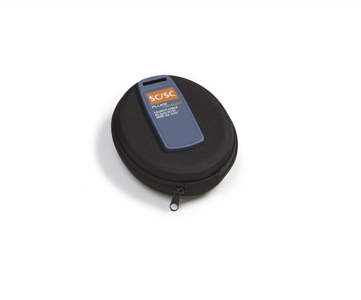
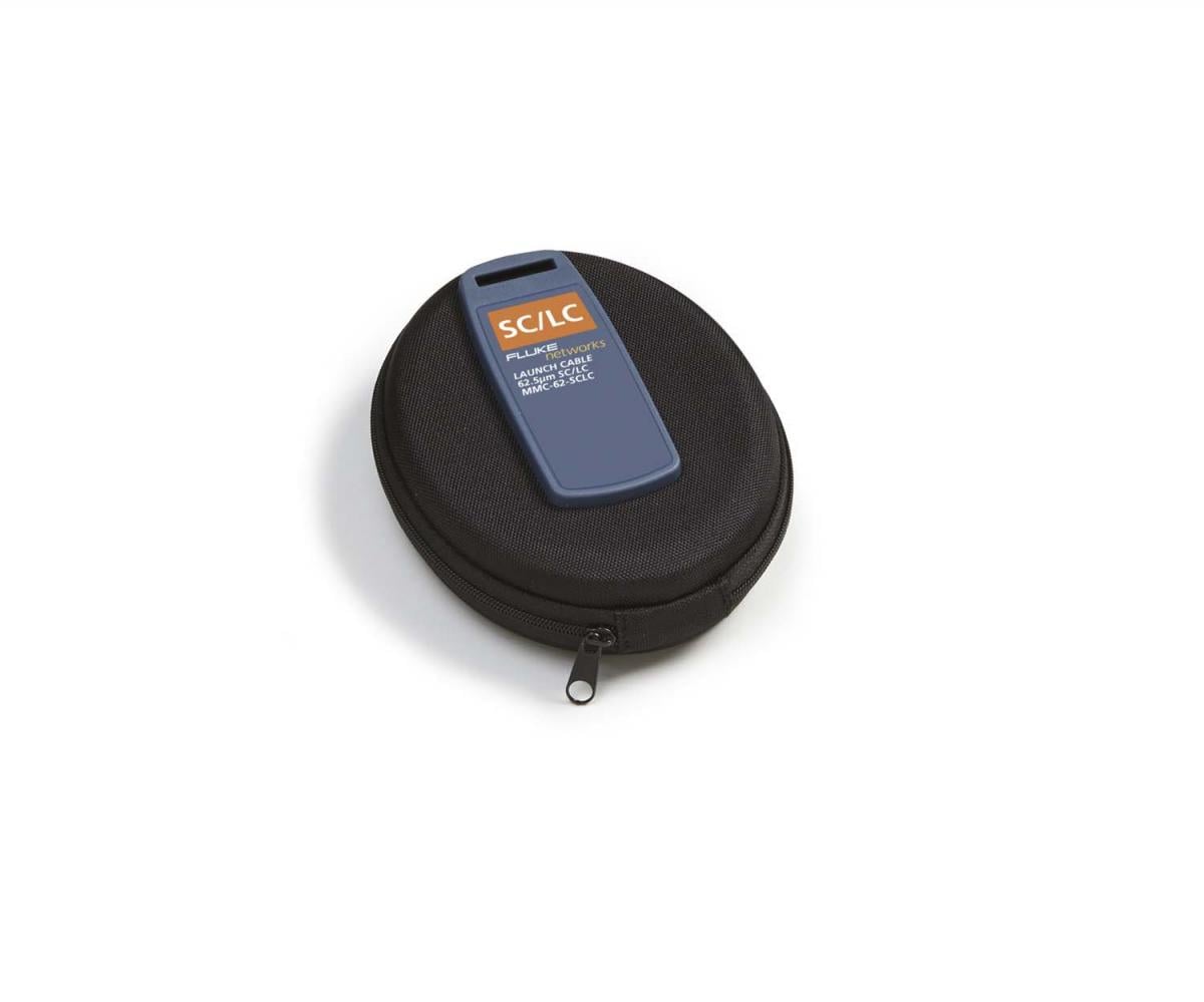
MMC-62-SCSC
MMC-62-SCSC
MMC-62-SCLC-M
MMC-62-SCLC-M
FI1000-2.5APC-UTIP
FI1000-2.5APC-UTIP
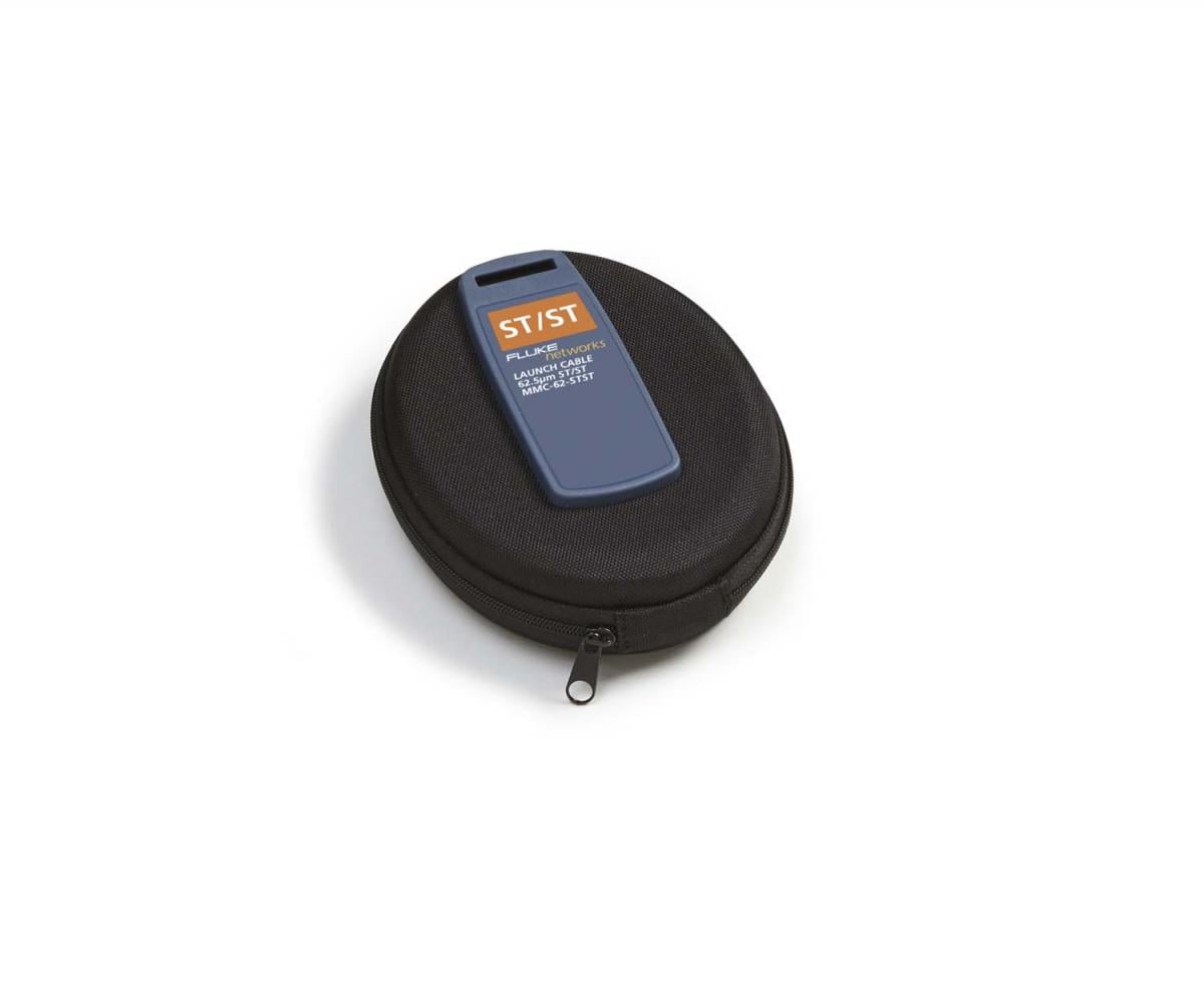
MMC-62-SCST
MMC-62-SCST
MMC-62-SCFC
MMC-62-SCFC
FI1000-1.25-UTIP
FI1000-1.25-UTIP
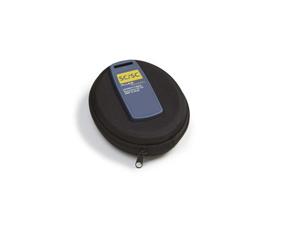
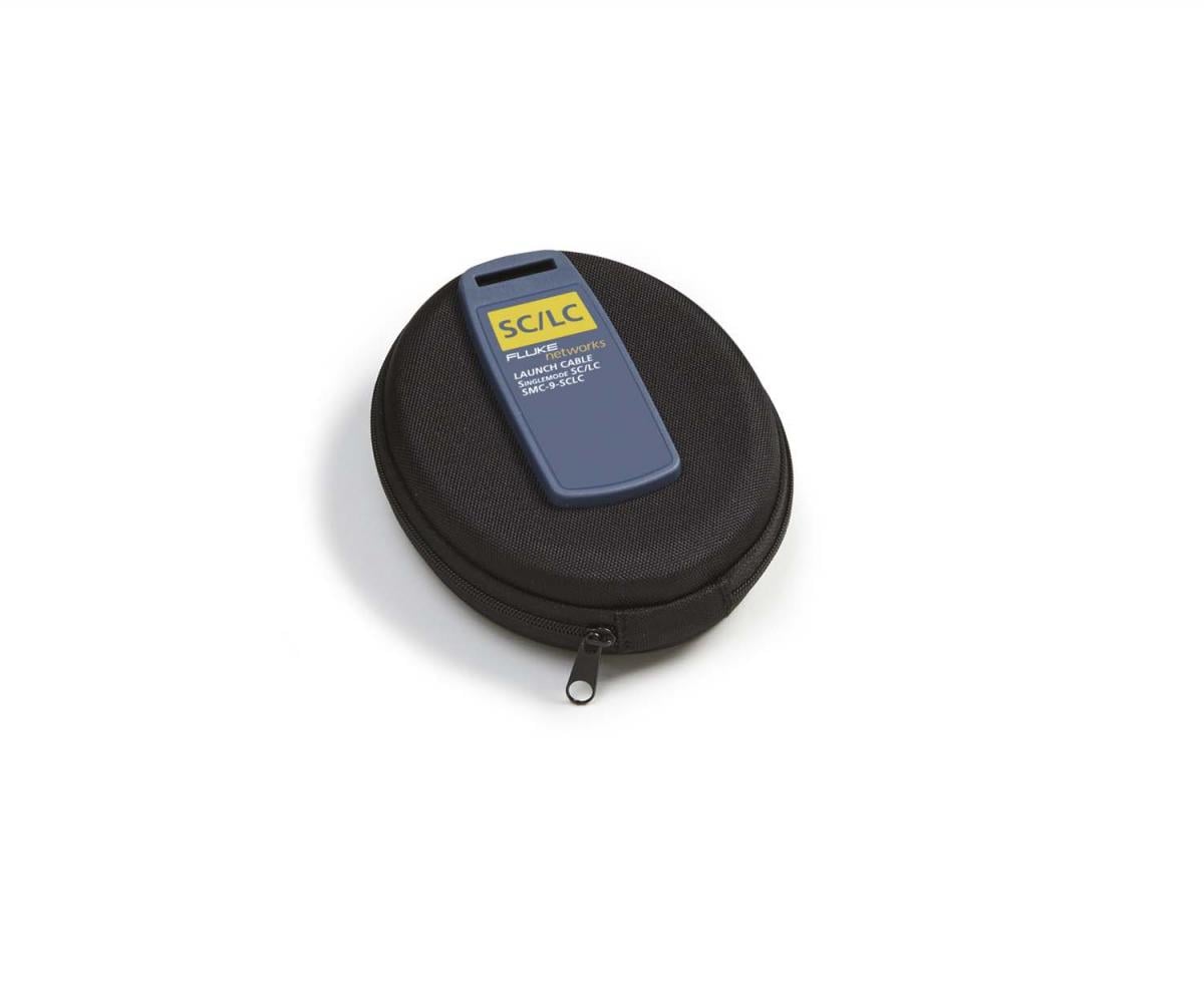
SMC-9-SCSC
SMC-9-SCSC
FI1000-2.5-UTIP
FI1000-2.5-UTIP
FI1000-LCAPC-TIP
FI1000-LCAPC-TIP
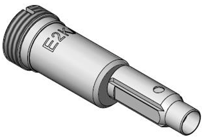
FI1000-E2K-TIP
FI1000-E2K-TIP
SMC-9-SCLC-M
SMC-9-SCLC-M
SMC-9-SCST
SMC-9-SCST
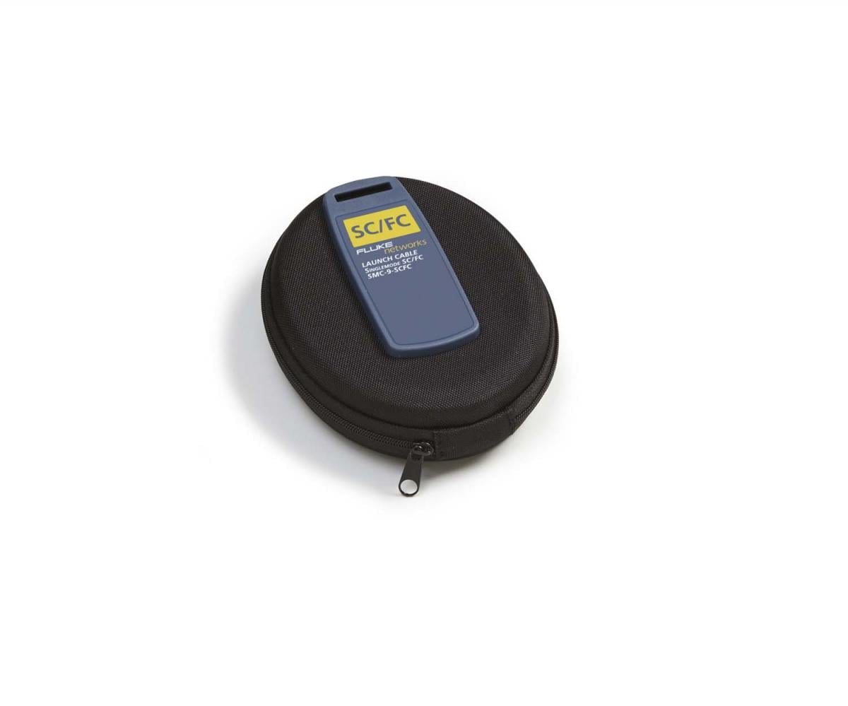
SMC-9-SCFC
SMC-9-SCFC
FI1000-SCAPC-TIP
FI1000-SCAPC-TIP
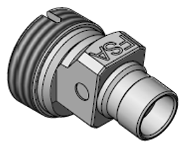
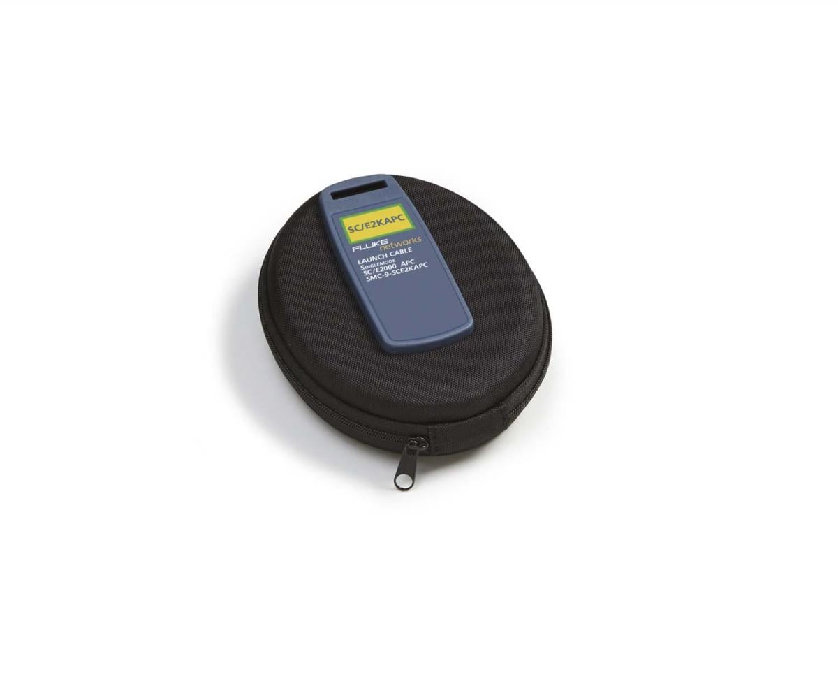
SMC-9-SCE2KAPC
SMC-9-SCE2KAPC
PA-SC
PA-SC
FI1000-E2KAPC-TIP
FI1000-E2KAPC-TIP
FI1000-MU-TIP
FI1000-MU-TIP
FI1000-ST-TIP
FI1000-ST-TIP
FI1000-LC-TIP
FI1000-LC-TIP
FI1000-SCFC-TIP
FI1000-SCFC-TIP
PA-ST
PA-ST
PA-FC
PA-FC
VERSIV-BATTERY
VERSIV-BATTERY
TFS-USB-CBL
TFS-USB-CBL
VERSIV-STRP
VERSIV-STRP
FI1000-MPOAPC-RT
FI1000-MPOAPC-RT
FI1000-MPO-RT
FI1000-MPO-RT
VERSIV-STND
VERSIV-STND
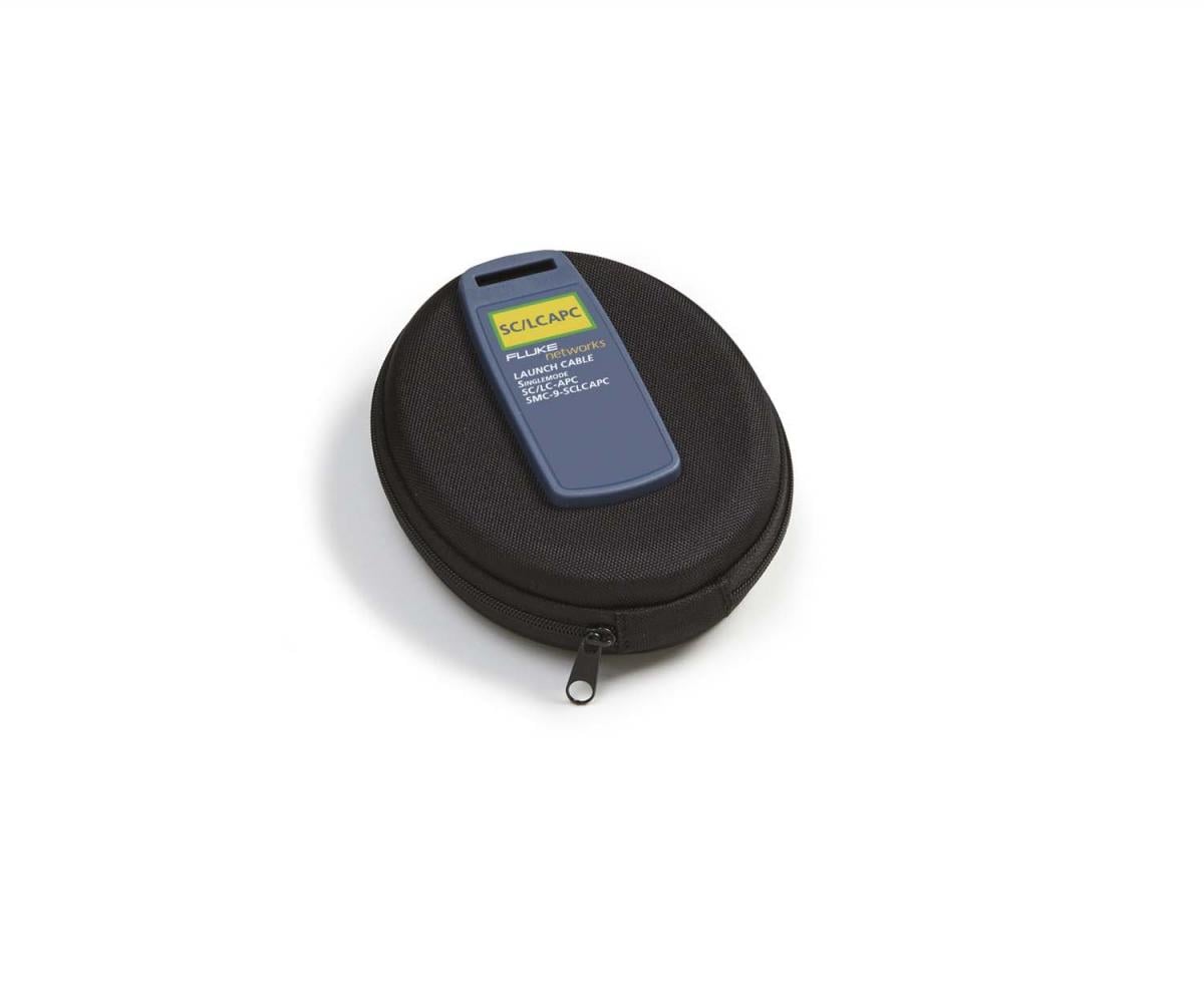
SMC-9-SCSCAPC
SMC-9-SCSCAPC
SMC-9-SCFCAPC
SMC-9-SCFCAPC
SMC-9-SCLCAPC-M
SMC-9-SCLCAPC-M
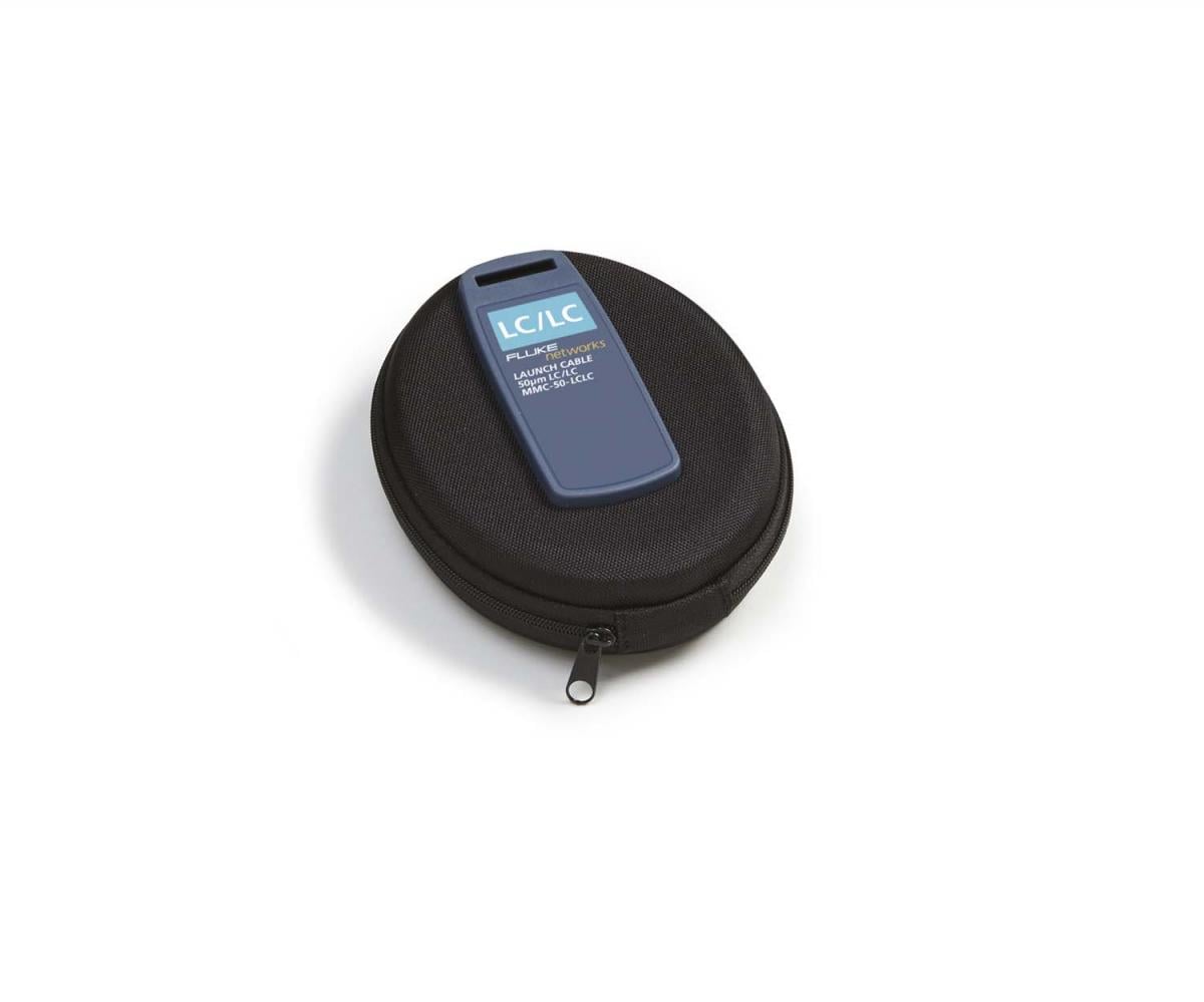
MMC-50-LCLC-M
MMC-50-LCLC-M
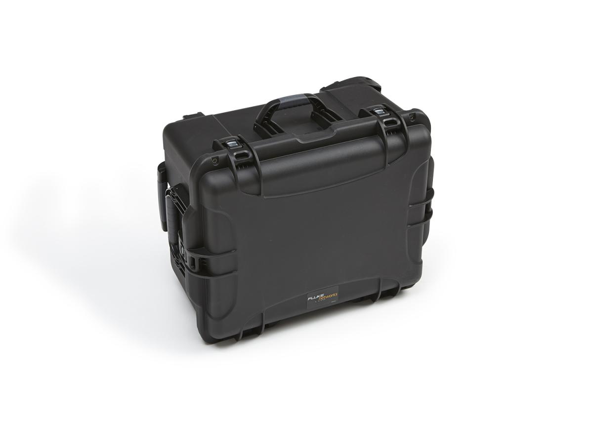
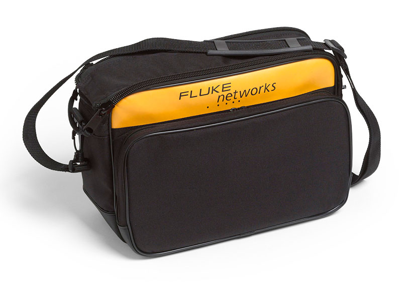
VERSIV-CASE3
VERSIV-CASE3
VERSIV-TSET
VERSIV-TSET
NFC-Kit-Case-E
NFC-Kit-Case-E
VERSIV2-RU
VERSIV2-RU
VERSIV2-M
VERSIV2-M
MMC-50-STST
MMC-50-STST
MMC-50-FCFC
MMC-50-FCFC
MMC-62.5-LCLC-M
MMC-62.5-LCLC-M
MMC-62.5-STST
MMC-62.5-STST
MMC-62.5-FCFC
MMC-62.5-FCFC
SMC-9-LCLC-M
SMC-9-LCLC-M
SMC-9-STST
SMC-9-STST
SMC-9-FCFC
SMC-9-FCFC
MRC-62.5-SCSC-0.3m
MRC-62.5-SCSC-0.3m
SRC-9-SCSC-0.3m
SRC-9-SCSC-0.3m
MRC-50-LCLC-0.3m-M
MRC-50-LCLC-0.3m-M
MRC-62.5-LCLC-0.3m-M
MRC-62.5-LCLC-0.3m-M
SRC-9-LCLC-0.3m-M
SRC-9-LCLC-0.3m-M
ADP-DuplexSC
ADP-DuplexSC
ADP-DuplexLC
ADP-DuplexLC
MRC-50-SCSC-0.3m
MRC-50-SCSC-0.3m
PA-LC
PA-LC
FI-1000 GOLD
FI-1000 Gold Support
FI-1000 USB video probe for Versiv products
GLD-FI-1000
1 year Gold Support coverage for FI-1000
GLD3-FI-1000
3 years of Gold Support coverage for FI-1000
VERSIV-SM-CASE
VERSIV-SM-CASE
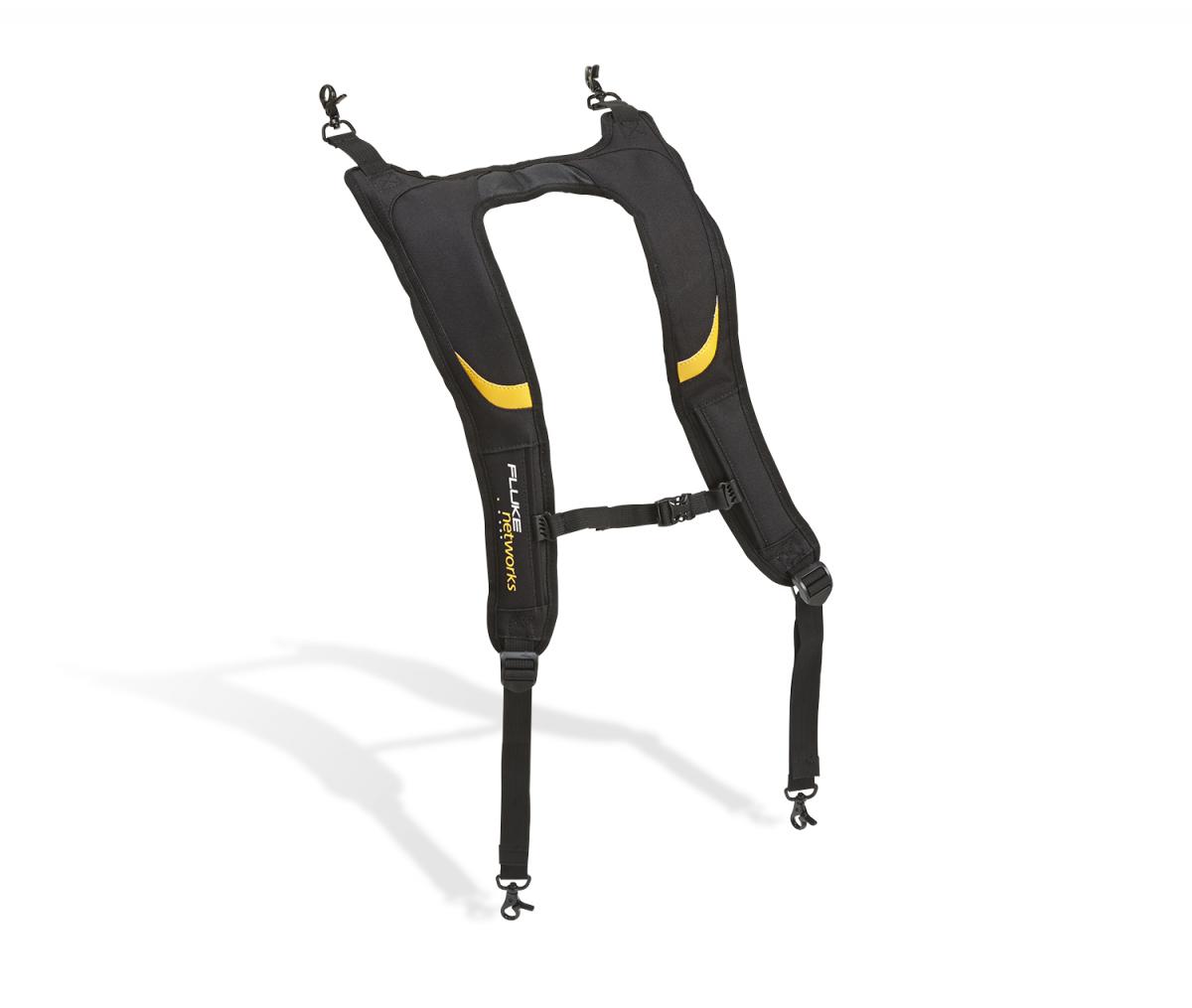
VERSIV-BACKPK-STRP
VERSIV-BACKPK-STRP
FI1000-EXND-LC-TIP
FI1000-EXND-LC-TIP
FI1000-LC-PCTIP
FI1000-LC-PCTIP
FI1000-MPO-XY-UTIP
FI1000-MPO-XY-UTIP
FI1000-MPOAPC-XY
FI1000-MPOAPC-XY
VERSIV-ADP-WIFI
VERSIV-ADP-WIFI
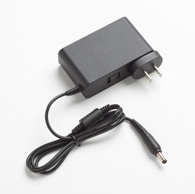
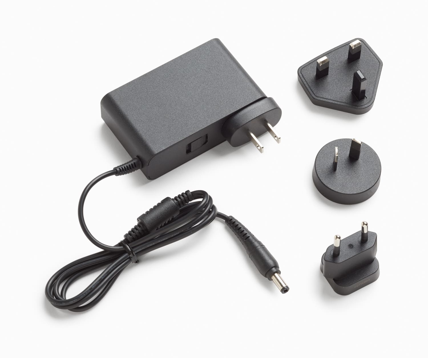
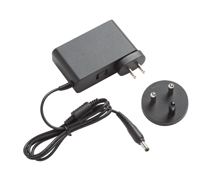
PWR-SPLY-30W
PWR-SPLY-30W
PWR-SPLY-30W INTL
PWR-SPLY-30W INTL
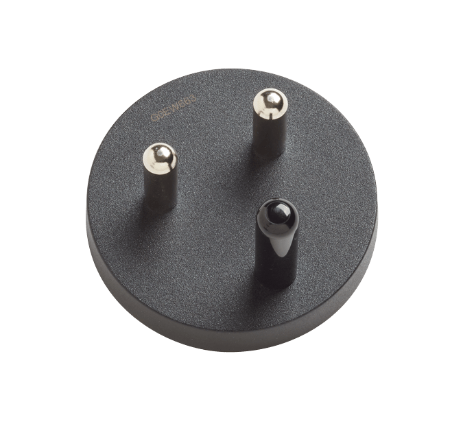
PWR-SPLY-30W SA/IN
PWR-SPLY-30W SA/IN
PWR-SPLY-ADP-SA
PWR-SPLY-ADP-SA
SMC-9-SCAPC/LC-M
SMC-9-SCAPC/LC-M
SMC-9-SCAPC/FC
SMC-9-SCAPC/FC
SMC-9-SCAPC/ST
SMC-9-SCAPC/ST
SMC-9-SCAPC/SCAPC
SMC-9-SCAPC/SCAPC
SMC-9-SCAPC/LCAPC-M
SMC-9-SCAPC/LCAPC-M
SMC-9-SCAPC/FCAPC
SMC-9-SCAPC/FCAPC
SMC-9-SCAPC/E2KAPC
SMC-9-SCAPC/E2KAPC
SMC-9-LCAPC/LCAPCM
SMC-9-LCAPC/LCAPCM
SMC-9-FCAPC/FCAPC
SMC-9-FCAPC/FCAPC
SMC9-E2KAPC/E2KAPC
SMC9-E2KAPC/E2KAPC
SRC9SCAPCSCAPC0.3m
SRC9SCAPCSCAPC0.3m
SRC9SCAPCLCAPC0.3mM
SRC9SCAPCLCAPC0.3mM
SRC-9-SCLC-0.3m
SRC-9-SCLC-0.3m
SRC9SCAPCSCUPC0.3m
SRC9SCAPCSCUPC0.3m
SRC-9-SCAPC/SCAPC
SRC-9-SCAPC/SCAPC
SRC-9-SCAPC/LCAPC-M
SRC-9-SCAPC/LCAPC-M
SRC-9-SCAPC/FCAPC
SRC-9-SCAPC/FCAPC
SRC-9-SCAPC/E2KAPC
SRC-9-SCAPC/E2KAPC
ADP-Duplex-SCAPC
ADP-Duplex-SCAPC
ADP-Duplex-LCAPC
ADP-Duplex-LCAPC
Versiv-Field-Case
Versiv-Field-Case
VERSIV2-M-NW
VERSIV2-M-NW
Versiv-XL-Case
Versiv-XL-Case
MMC-50-SCST
MMC-50-SCST
VERSIV2 M/RU KIT
VERSIV2 M/RU KIT
VERSIV2 M/RU-NW KIT
VERSIV2 M/RU-NW KIT
Specifications
Key OptiFiber Pro OTDR specifications
| Multimode module | Singlemode module | Quad module | |
| Wavelengths | 850 nm +/- 10 nm 1300 nm +35/-15 nm | 1310 nm +/- 25 nm 1550 nm +/- 30 nm | 850 nm +/- 10 nm 1300 nm +35/-15 nm 1310 nm +/- 25 nm 1550 nm +/- 30 nm |
| Compatible fiber types | 50/125 µm 62.5/125 µm | Singlemode | 50/125 µm 62.5/125 µm Singlemode |
| Event dead zone 1 | 850 nm: 0.5 m typical 1300 nm: 0.7 m typical | 1310 nm: 0.6 m typical 1550 nm: 0.6 m typical | 850 nm: 0.5 m typical 1300 nm: 0.7 m typical 1310 nm: 0.6 m typical 1550 nm: 0.6 m typical |
| Attenuation dead zone 2 | 850 nm: 2.5 m typical 1300 nm: 4.5 m typical | 1310 nm: 3.6 m typical 1550 nm: 3.7 m typical | 850 nm: 2.5 m typical 1300 nm: 4.5 m typical 1310 nm: 3.6 m typical 1550 nm: 3.7 m typical |
| Dynamic range 3, 5, 6 | 850 nm: 28 dB typical 1300 nm: 30 dB typical | 1310 nm: 32 dB typical 1550 nm: 30 dB typical | 850 nm: 28 dB typical 1300 nm: 30 dB typical 1310 nm: 32 dB typical 1550 nm: 30 dB typical |
| Max distance range setting | 40 km | 130 km | MM: 40 km SM: 130 km |
| Distance measurement range 4, 5, 7, 8, 9, 10 | 850 nm: 9 km 1300 nm: 35 km | 1310 nm: 80 km 1550 nm: 130 km | 850 nm: 9 km 1300 nm: 35 km 1310 nm: 80 km 1550 nm: 130 km |
| Reflectance range 4, 5 | 850 nm: -14 dB to -57 dB (typical) 1300 nm: -14 dB to -62 dB (typical) | 1310 nm: -14 dB to -65 dB (typical) 1550 nm: -14 dB to -65 dB (typical) | 850 nm: -14 dB to -57 dB (typical) 1300 nm: -14 dB to -62 dB (typical) 1310 nm: -14 dB to -65dB (typical) 1550 nm: -14 dB to -65 dB (typical) |
| Sample resolution | 3 cm to 400 cm | ||
| Pulse widths (nominal) | 850 nm: 3, 5, 20, 40, 200 ns 1300 nm: 3, 5, 20, 40, 200, 1000 ns | 1310/1550 nm: 3, 10, 30, 100, 300, 1000, 3000, 10000, 20000 ns | 850 nm: 3, 5, 20, 40, 200 ns 1300 nm: 3, 5, 20, 40, 200, 1000 ns 1310/1550 nm: 3, 10, 30, 100, 300, 1000, 3000, 10000, 20000 ns |
| Test time (per wavelength) | Auto setting: 5 sec (typical) Quick test setting: 2 sec (typical) Best resolution setting: 2 to 180 sec FaultMap setting: 2 sec (typical), 180 sec (max) DataCenter OTDR setting: 1 sec (typical at 850 nm), 7 sec (max) Manual setting: 3, 5, 10, 20, 40, 60, 90, 120, 180 sec | Auto setting: 10 sec (typical) Quick test setting: 5 sec (typical) Best resolution setting: 5 to 180 sec FaultMap setting: 10 sec (typical), 180 sec (max) DataCenter OTDR setting: 20 sec (typical), 40 sec (max) Manual setting: 3, 5, 10, 20, 40, 60, 90, 120, 180 sec | Auto setting: MM – 5 sec (typical), SM – 10 sec (typical) Quick test setting: MM – 2 sec (typical), SM – 5 sec (typical) Best resolution setting: MM – 2 to 180 sec, SM – 5 to 180 sec FaultMap setting: MM - 2 sec (typical)/180 sec (max), SM - 10 sec (typical)/180 sec (max) DataCenter OTDR setting: MM – 1 sec (typical at 850 nm)/7 sec (max), SM – 20 sec (typical)/40 sec (max) Manual setting: 3, 5, 10, 20, 40, 60, 90, 120, 180 sec |
| 1. Measured at 1.5 dB below non-saturating reflection peak with the shortest pulse width. Reflection peak < -40 dB for multimode and < - 50 dB for singlemode. 2. Measured at +/- 0.5 dB deviation from backscatter with the shortest pulse width. Reflection peak < -40 dB for multimode and < - 50 dB for singlemode. 3. For typical backscatter coefficient for OM1 fiber: 850: -65 dB, 1300: -72 dB. 4. Typical backscatter and attenuation coefficients for OM2-OM4 fiber: 850 nm: -68 dB; 2.3 dB/km: 1300 nm: -76 dB; 0.6 dB/km. 5. Typical backscatter and attenuation coefficients for OS1-OS2 fiber: 1310nm : -79 dB; 0.32 dB/km; 1550 nm: -82 dB; 0.19 dB/km. 6. SNR=1 method, 3 minute averaging, widest pulse width. 7. 850 = 9 km typical to find the end or 7 km typical to find a 0.1 dB event (with a maximum of 18 dB attenuation prior to the event). | |||
Key OptiFiber Pro HDR Specification
| 1310/1550 nm | 1310/1490/1550 nm | 1310/1550/1625 nm | |
| Wavelengths | 1310 nm +/- 25 nm 1550 nm +/- 20 nm | 1310 nm +/- 25 nm 1490 nm +/- 20 nm 1550 nm +/- 20 nm | 1310 nm +/- 25 nm 1550 nm +/- 20 nm 1625 nm +/- 20 nm |
| Compatible fiber types | Singlemode | Singlemode | Singlemode |
| OTDR Port Connector | Cleanable APC ferrule with removable SC adapter | Cleanable APC ferrule with removable SC adapter | Cleanable APC ferrule with removable SC adapter |
| Event dead zone 1 | 0.7 m (typical) | 0.7 m (typical) | 0.7 m (typical) |
| Attenuation dead zone 2 | 4m (typical) | 4m (typical) | 4m (typical) |
| PON dead zone 3 | 30 m (typical) | 30 m (typical) | 30 m (typical) |
| Max distance range setting | 260 km | 260 km | 260 km |
| Dynamic range 4, 5 | 1310 nm: 42 dB (typical) 1550 nm: 41 dB (typical) | 1310 nm: 42 dB (typical) 1490 nm: 41 dB (typical) 1550 nm: 41 dB (typical) | 1310 nm: 42 dB (typical) 1550 nm: 41 dB (typical) 1625 nm: 40 dB (typical) |
| Reflectance range 4 | -14 to -70 dB (typical) | -14 to -70 dB (typical) | -14 to -70 dB (typical) |
| Sampling resolution | 3 cm to 2 m | 3 cm to 2 m | 3 cm to 2 m |
| Sampling points | Up to 129000 | Up to 129000 | Up to 129000 |
| Pulse widths (nominal) | 5, 10, 30, 50, 100, 300, 500, 1000, 3000, 5000, 10000, 20000 ns | 5, 10, 30, 50, 100, 300, 500, 1000, 3000, 5000, 10000, 20000 ns | 5, 10, 30, 50, 100, 300, 500, 1000, 3000, 5000, 10000, 20000 ns |
| Distance uncertainty | +/-(1 + 0.0005*distance + 0.5*resolution) | +/-(1 + 0.0005*distance + 0.5*resolution) | +/-(1 + 0.0005*distance + 0.5*resolution) |
| Linearity | ± 0.03 dB/dB | ± 0.03 dB/dB | ± 0.03 dB/dB |
| Reflectance uncertainty | ±2 dB | ±2 dB | ±2 dB |
| Test Time (per wavelength) | Auto setting: 5 seconds/wavelength (typical) Auto PON setting: 10 seconds/wavelength (typical) Manual setting: 3, 5, 10, 20, 40, 60, 90, 120, 180 seconds/wavelength Manual PON setting: 3, 5, 10, 20, 40, 60, 90, 120, 180 seconds/wavelength Quick test setting: 3 seconds/wavelength (typical) Best resolution setting: 5 to 180 seconds/wavelength | Auto setting: 5 seconds/wavelength (typical) Auto PON setting: 10 seconds/wavelength (typical) Manual setting: 3, 5, 10, 20, 40, 60, 90, 120, 180 seconds/wavelength Manual PON setting: 3, 5, 10, 20, 40, 60, 90, 120, 180 seconds/wavelength Quick test setting: 3 seconds/wavelength (typical) Best resolution setting: 5 to 180 seconds/wavelength | Auto setting: 5 seconds/wavelength (typical) Auto PON setting: 10 seconds/wavelength (typical) Manual setting: 3, 5, 10, 20, 40, 60, 90, 120, 180 seconds/wavelength Manual PON setting: 3, 5, 10, 20, 40, 60, 90, 120, 180 seconds/wavelength Quick test setting: 3 seconds/wavelength (typical) Best resolution setting: 5 to 180 seconds/wavelength |
| Laser Classification | Class 1 CDRH Complies to EN 60825-2, 3rd Edition | Class 1 CDRH Complies to EN 60825-2, 3rd Edition | Class 1 CDRH Complies to EN 60825-2, 3rd Edition |
| Calibration Period | 1 year | 1 year | 1 year |
| 1. Measured at 1.5 dB below non-saturating reflection peak with the shortest pulse width. Reflection peak at - 50 dB. 2. Measured at +/- 0.5 dB deviation from backscatter with the shortest pulse width. Reflection peak‹ - 50 dB. 3. Measured at +/- 0.5 dB deviation from backscatter after 1:16 non-reflective splitter using 50 ns pulse width and 3 cm sampling resolution. 4. Typical backscatter coefficients for OS1-OS2 fiber: 1310 nm: -79 dB; 1490 nm: -81 dB; 1550 nm: -82 dB; 1625 nm: -84 dB. 5. 3 minute averaging, widest pulse width, 100 km fiber length, SNR = 1. | |||
Additional key specifications
FiberInspector probe specification
| Magnification | ~ 200X with OptiFiber Pro Display |
| Light source | Blue LED |
| Power source | Versiv mainframe |
| Field of View (FOV) | Horizontal: 425 µm Vertical: 320 µm |
| Minimum detectable particle size | 0.5 µm |
| Dimensions | Approximately 6.75 in x 1.5 in (1175 mm x 35 mm) without adapter tip |
| Weight | 200 g |
| Temperature range | Operating: 32°F to 122°F (0 °C to +50 °C) Storage: -4°F to +158°F (-20°C to +70°C) |
| Certifications | CE (when used with the mainframe) |
VFL specifications
| On/Off control | Mechanical switch and a button on the touch screen |
| Output power | 316 µW (-5 dBm) = peak power = 1.0 mW (0 dBm) |
| Operating wavelength | 650 nm nominal |
| Spectral width (RMS) | ±3 nm |
| Output modes | Continuous wave Pulsed mode (2 Hz to 3 Hz blink frequency) |
| Connector adapter | 2.5 mm universal |
| Laser safety (classification) | Class II CDRH Complies to EN 60825-2 |
General specifications
| Weight | Mainframe with module and battery: 3 lbs, 5 oz (1.28 kg) |
| Dimensions | Mainframe with module and battery: 2.625 in x 5.25 in x 11.0 in ( 6.67 cm x 13.33 cm x 27.94 cm) |
| Battery | Lithium ion battery pack, 7.2 volts |
| Battery life | Eight hour Auto OTDR operation, dual wavelength, no video probe connected, 150 m of fiber |
| Integrated Wi-Fi | Meets IEEE 802.11 a/b/g/n; dual band (2.4 GHz and 5 GHz) |
| Charge Time | |
| Tester Off | Four hours to charge from 10% to 90% capacity |
| Tester On | Six hours to charge from 10% to 90% capacity with the tester on |
Environmental specifications
| Operating temperature* | -10ºC to 45ºC |
| Storage Temperature | -10ºC to +60ºC |
| Operating altitude | 4,000 m (13123 ft) 3200 m (10,500 ft) with ac adapter |
| Storage altitude | 12,000 m |
| EMC | EN 61326-1 |
| * Using battery power. With AC power: 0ºC to 45ºC. Real Time Trace function used for no more than 5 minutes in a 15-minute period. Maximum ambient temperature is 35ºC for continuous use of the Real Time Trace function. * Do not keep battery at temperatures below -20°C (-4°F) or above 50°C (122°F) for periods longer than one week to maintain battery capacity. | |
Documents
Manuals
- OptiFiber Pro Getting Started Guide User documentation Download PDF
- Versiv Series Technical Reference Handbook, Rev. 13 User documentation for Versiv firmware Download PDF
- Guida introduttiva del OptiFiber Pro (Italiano) Documentazione per l'utente Download PDF
- OptiFiber Pro Başlangıç Kılavuzu (Türkçe) Kullanıcı belgeleri Download PDF
- Versiv Series Users Manual, Rev. 9 User documentation for Versiv firmware Download PDF
- OptiFiber Pro HDR OTDR Getting Started Guide User documentation Download PDF
- Guida introduttiva del OptiFiber Pro HDR OTDR (Italiano) Documentazione per l'utente Download PDF
- OptiFiber Pro HDR OTDR Başlangıç Kılavuzu (Türkçe) Kullanıcı belgeleri Download PDF
- Versiv™ Series Cabling Certification Product Family - Safety Information Download PDF
Data Sheets
White Papers
- Choosing The Right OTDR White Paper Download PDF
- White Paper: Fiber Contamination, Cleaning and Inspection. Introduction. Download PDF
- The Ins and Outs of Testing Bend Insensitive Multimode Fiber (BIMMF): The Need for Encircled Flux Download PDF
- Spend Less Time Making Better Fiber Measurements Download PDF
- White Paper: Troubleshooting Fiber Download PDF
- 8 Reasons Upgrading to Versiv will “Cut Your Certification Costs by 65% Download PDF
- OLTS & OTDR: A Complete Testing Strategy Download PDF
Application Notes
- Fiber Testing Best Practices - Pocket Guide Request your 4” x 6”, sturdy pocket guide that is ideal to take on all your fiber jobs. Includes a quick-action summary and checklist, this guide is an invaluable tool to ensure you never miss a critical step during your fiber testing or troubleshooting. Download PDF
Flyers
手册
白皮书
传单
Handbücher
Technischer Anwendungsbericht
Manuales
Fichas técnicas
Documentos Técnicos
Hoja Publicitaria
Manuels
Fiches techniques
Livres blancs
マニュアル
ホワイトペーパー
カタログ
설명서
백서
Manuais
Planilha de dados
White Papers
Case Studies
CompuCom Case Study
Challenge:
Headquartered in Dallas, Texas, CompuCom enables its customers to focus on their respective core businesses, while CompuCom handles their technology. Offering managed IT services, integration and consulting, as well as teams specializing in data centers, networks, voice and end-user environments, CompuCom supports more than four million users in North America alone. One of CompuCom's customers, a U.S.-based Top 10 Global Retailer, required a higher standard for fiber optic cable inspection, including faster testing and more comprehensive reporting. In response, CompuCom’s team turned to Fluke Networks.
Results:
As part of its service to this retailer, the CompuCom team maintains three data centers plus one backup bunker, containing nearly 20,000 servers and more than 150,000 cables. The team chose to adopt the Fluke Networks Versiv cable certification platform with a combination of the FI-7000 FiberInspector™ Pro, OptiFiber® Pro OTDR, and CertiFiber® Pro cable loss testing modules to provide easy repairs and upgrades. Since adopting the FI-7000 when it was first launched, the team has dramatically raised the standards in testing and reporting, while also simplifying test result accessibility and management. The FI-7000 enables faster test results, which have saved thousands of dollars each year. Most important, CompuCom's client has been very pleased with the higher levels of speed, quality and reliability made possible with the FI-7000. So much so, that this client now holds other service providers to similar standards.

Integrity Networks Alaska Branch Case Study
The Ultimate Test in the Alaskan Bush Survival Tip: Take care where the bears roam
Company Background
Integrity Networks provides communications services and cable and fiber network infrastructure installation for companies and federal, state and local governments nationwide and around the Pacific Rim. Based in Renton, Washington, their projects range from military bases in Guam and Singapore, data center and VOIP installations in Washington and Virginia, to major healthcare and corporate oil, gas and mining projects across Alaska.
Integrity Networks entered the Alaskan market in 2007, and it has remained a steady presence in low-voltage contracting there ever since. With branch headquarters in Anchorage, Integrity Networks has an extensive staff of highly skilled Alaskan employees that work on jobs in the last great American frontier.
![]()
Twistnet Communications Ltd Case Study
EXTREME DANGER: High Voltage Environment
With Fluke Networks OptiFiber® Pro OTDR with SmartLoop™, Twistnet technicians safely completed bidirectional certification of new North Sea Wind Farm installation
Company Background
Established in 2000, with more than 30 years of experience, Twistnet Communications Ltd. specializes in the installation, testing and certification of fiber optic cabling, structured cabling systems and voice cabling systems.
Twistnet Communications Ltd serves companies in the United Kingdom and Europe with core services and it offers experts in fusion splicing, direct fiber termination, OTDR and power-meter testing and certification and repair with state of the art equipment such as the Fluke Networks' OptiFiber Pro OTDR with SmartLoop, part of the Versiv™ line, the industry’s leading Cabling Certification System
![]()
LAN NET Solutions Case Study
LAN NET Solutions LLC Wins OptiFiber Pro In LinkWare Live Rewards Program
Texas-based LAN NET Solutions is the winner of the Fluke Networks LinkWare Live Rewards Program. As the saying goes, everything’s big in Texas, and the OptiFiber Pro prize that big winner LAN NET Solutions won is One Big Prize.
