
WHITE PAPER
Third-Generation Multi-Fiber Testing: The Definitive Standard for Complex Modern Data Centers
Overview
Over the past few decades, the volume of fiber optic cabling in the data center has grown exponentially, enabling ever-faster transmission speeds to support our increasingly digital world. Central to this evolution is the emergence of multi-fiber connectivity, which originated with multi-fiber push-on (MPO) connectors as an ideal plug-and-play solution for consolidating duplex fiber backbones and supporting the first waves of high-speed parallel optic applications.

Today, hyperscale cloud demands and the rise of artificial intelligence (AI) are pushing transmission speeds and fiber densities to unprecedented heights. This surge has made multi-fiber connectivity vastly more pervasive across the data center while requiring denser, smaller, and more complex connectors — a shift that renders legacy multi-fiber testing solutions fundamentally inadequate.
Modern high-density and AI-driven data centers have outgrown legacy multi-fiber testing methods. In environments where uptime is non-negotiable and data integrity is paramount, the arrival of third-generation multi-fiber testing is not just an upgrade; it is a high-stakes necessity for complex modern data centers to ensure their ultra-dense fiber links deliver the application assurance required by today's high-performance, data-intensive architectures.
The rise of multi-fiber connectors: from duplex backbones to 1.6 terabit
MPO connectors house an array of fibers in a single ferrule, available in multimode and single-mode versions with fiber counts such as 8, 12, 16, 24, and 32. Precise mechanical alignment is maintained with pinned (male) MPO connectors that always mate with unpinned (female) MPO connectors. Because active equipment almost always features pinned interfaces, any connecting MPO cables must be unpinned. MPOs are also keyed and marked with a white dot that indicates the first fiber position to aid in correct orientation and polarity when joining components via adapters.
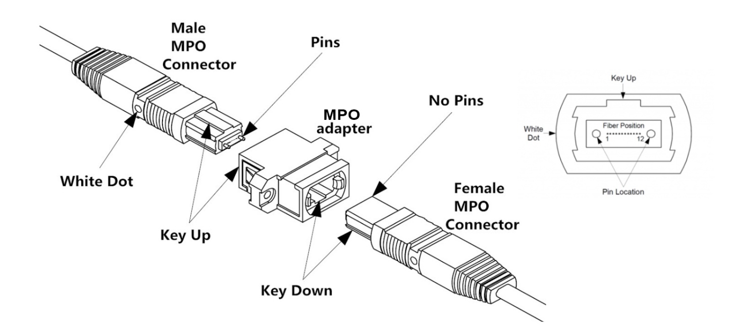
The adoption of 12-fiber MPOs gained traction in the early 2000s as a plug-and-play solution to consolidate duplex backbone cabling. Rather than pulling dozens of individual duplex cables, technicians could easily deploy far fewer MPO trunk cables between patching areas and use MPO-to-LC cassettes to break them out into standard duplex connections. The landscape then shifted with the introduction of parallel optic applications that transmit data streams across multiple fibers simultaneously using MPOs.
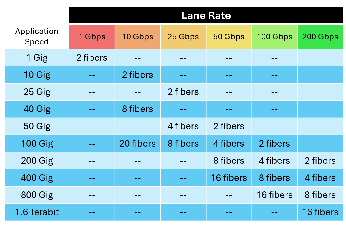
As signaling technology continued to advance and support increasingly faster lane rates, MPOs became the foundation for the modern data center, where 12-fiber MPOs support 400 Gig and 16-fiber MPOs support 800 Gig. The upcoming IEEE 802.3dj, expected by mid-2026, will leverage a 200 Gbps lane rate, allowing 12-fiber MPOs to support 800 Gig and 16-fiber MPOs to support 1.6 Terabit. These advanced speeds, enabled by MPOs, support switch connections and are critical for GPU interconnects within AI clusters. MPOs also continue to streamline infrastructure by consolidating backbone cabling, such as using a 24-fiber MPO trunk cable between patching areas to transition to three 8-fiber MPO connections.
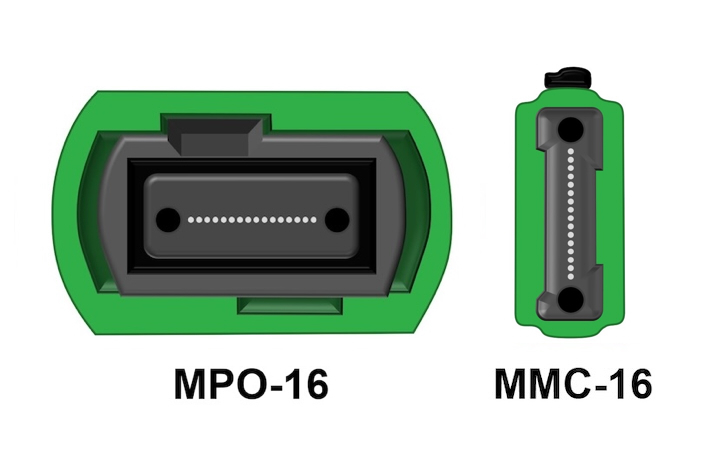
As today's data centers pack in more equipment operating at ever-increasing speeds to support cloud computing and interconnect thousands of GPUs for AI, fiber densities continue to rise. This has spurred the development of very small form factor (VSFF) multi-fiber connectors, such as the MMC (multi-fiber micro connector) from US Conec. Available in 12- and 24-fiber variants, MMCs stack fibers vertically in a much smaller housing to maximize space in high-density environments.
"MMC has achieved widespread adoption as AI data centers scale at unprecedented rates. Using high-performance TMT ferrule technology, MMC delivers triple the density of MPO connectors and offers mass-insertion solutions that accelerate deployment in today's high-density networks," said Charlie Stroup, Applications Engineering Manager at US Conec. To put the size difference into context, 216 16-fiber MMC connectors fit in the same space as 80 traditional 16-fiber MPO connectors.
Ensuring performance: the critical role of certification
Whether you are a cloud provider rolling out AI or an enterprise undergoing digital transformation, fiber certification testing is the only way to guarantee that multi-fiber links meet the bandwidth, speed, and latency requirements of modern data center applications. Certification testing also verifies that installed links meet design specifications, secures warranties, proves the quality of an installation, and provides performance benchmarks for future troubleshooting.
Certification testing is performed using an Optical Loss Test Set (OLTS), consisting of main and remote units that work in concert as a light source and power meter to measure insertion loss and link length. Insertion loss is the energy a signal loses as it travels along the links, expressed in decibels (dB). If the loss is too high, active equipment cannot correctly interpret the signal. Whether a link passes or fails certification testing depends on the maximum loss values and link lengths published in industry standards for specific applications. With high-speed applications demanding more stringent loss requirements, certification testing has transformed from a best practice to a fundamental requirement for guaranteed network performance.
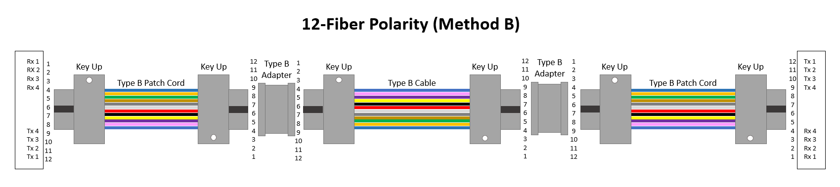
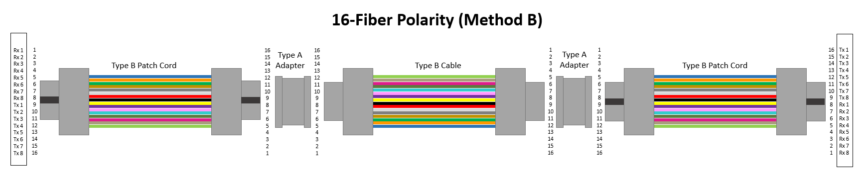
Beyond loss and length, certification testing verifies polarity, ensuring transmit (Tx) signals at one end match the corresponding receivers (Rx) at the other. For example, for 8-fiber applications using 12-fiber MPOs, the fiber located in Position 1 must arrive at Position 12. For 16-fiber applications using 16-fiber MPOs, the fiber located in Position 1 must arrive at Position 16. Maintaining polarity grows increasingly complex with multi-fiber connectivity and multi-segment channels, making a polarity-verifying certification tester vital. When polarity is not maintained, the transmit signal at one end will not match the corresponding receiver at the other end, resulting in a non-functional channel.
Achieving accurate results: the value of the 1-jumper reference
To accurately measure a link, it is essential to include the loss of both the first and last connectors, as this reflects how the link will ultimately be used. Since it is impossible to measure the loss of a single connector, connector loss must be calculated as the loss of a mated pair. This requires Test Reference Cords (TRCs) — high-quality multi-fiber cables that connect the tester to the link under test.
Before testing, the tester must be calibrated to 0 dB to reference out the loss of any TRCs. It is like placing a bowl on a scale and zeroing it to ensure the accurate weight of its contents. There are three primary methods for setting the reference:
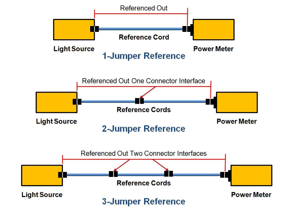
- 1-jumper reference (preferred): It is the default method recommended by industry standards that offers the least uncertainty in the measurement. It references out the TRC so that the final measurement correctly includes the loss of the connections at both ends. It requires the TRC and tester interface to match the connector type under test.
- 2-jumper reference (not recommended): This method yields the highest uncertainty of all reference methods and provides only a partial depiction of the total loss. It references out the mated connection between the two jumpers, resulting in a final measurement that includes only one end connection.
- 3-jumper reference method (use when a 1-jumper method is not feasible): When the connector type on your TRC and tester does not match the connector type of the link under test, the 3-jumper reference is used. It references out two connector pairs and requires a more complex process using a substitution cord to account for the loss of the first and last connectors.
Once the reference is established, the best practice is to verify TRC performance. TRCs can wear out over time, and verification ensures that link failures are caused by the cabling itself rather than a degraded TRC. Once the reference is set and the TRC performance is verified, it must remain connected to the tester's output port during testing. Disconnecting the TRC at any point invalidates the reference, requiring it to be reset.
Correctly setting the reference before testing is a vital step in ensuring the integrity of the test results. If the reference is flawed — or if the TRC is removed and replaced without resetting the reference — every subsequent test measurement will be compromised. This leads to unreliable data, ranging from deceptively optimistic results and false passes to physically impossible negative loss readings.
Inspection and cleaning: an essential step
Contaminated fiber end faces are a primary cause of fiber link failures in the data center. Dirty end faces can cause signal loss and reflections that degrade performance. They can also damage the ports on expensive data center switches, routers, and servers. Proper inspection is especially critical for multi-fiber connectors, since contaminants from one fiber can easily migrate to another within the same array. Every connector should be inspected and, if necessary, cleaned before mating to check for dirt, scratches, and other end-face irregularities — even factory-terminated multi-fiber connectors fresh out of the bag.
Inspection begins with examination of the entire ferrule using a large-field-of-view (LFOV) microscope with an inspection tip that matches the specific multi-fiber connector type. A critical distinction of single-mode multi-fiber connectors is that they feature angled physical contact (APC) fiber end faces that reduce reflections in the fiber core — it is virtually impossible to achieve good reflectance across multiple flat ultra-physical contact (UPC) single-mode fiber end faces. APC inspection tips are required when inspecting single-mode multi-fiber connectors to obtain an adequate view of the entire end face. Fluke Networks FI-3000 FiberInspector™ Ultra Camera comes standard with tips for inspecting both UPC and APC 8-, 12-, and 24-fiber MPO end faces, with accessory tips available for inspecting 16- and 32-fiber MPOs and VSFF MMC connectors.
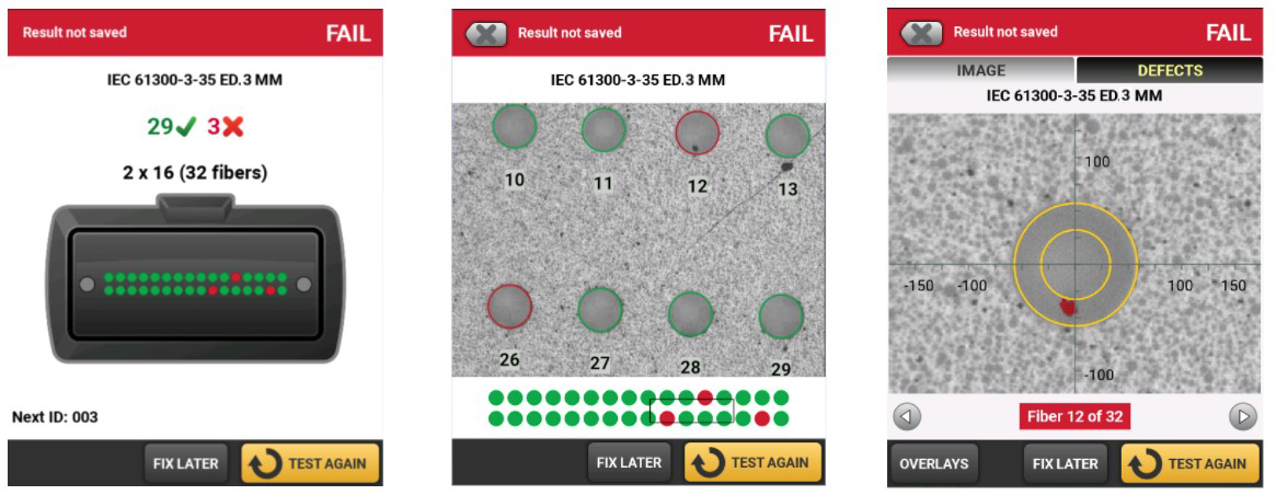
Another key consideration for inspecting multi-fiber connectors is the ability to view both the entire connector array and individual fibers. Advanced inspection tools like the FI-3000 feature dual cameras that provide a single, integrated view of the entire array, along with the ability to zoom in on a specific area, pan across the connector, or focus on an individual fiber end face for a detailed look. The best inspection tools remove human subjectivity and inconsistency by automating certification of connector cleanliness based on the number and size of defects in the critical zones of each fiber end face, as defined in IEC 61300-3-35. The FI-3000 uses algorithmic processes to quickly inspect, grade, and certify end faces against IEC standards, providing automated PASS/FAIL results for each fiber in a multi-fiber connector. It even offers PortBright™ illumination for inspecting connectors in dark and crowded data center environments.
Cleaning should only be performed if the inspection reveals contamination. Unnecessary cleaning risks introducing new contaminants or damaging the fiber end faces. Only cleaners, solvents, wipes, or swabs specially formulated for fiber optics should be used. One-push mechanical cleaners are highly effective at removing common contaminants like dust, skin oil, and lint from multi-fiber connectors. Always re-inspect connectors after cleaning. If a connector fails inspection after several cleaning attempts but passes certification testing, it is still considered suitable for use.
The evolution of multi-fiber testing: from manual workarounds to automated precision
Early multi-fiber testing was a cumbersome, manual process. Technicians relied on duplex fiber certification testers, a 3-jumper reference method, and MPO-to-LC fan-out cords or cassettes. This involved moving the tester from fiber to fiber to calculate loss for each pair (send and receive), a process that was not only time-consuming but also increased the risk of contaminating the end faces during repeated reconnections and required complex referencing and tracking of polarity across multiple fibers.
The arrival of first-generation MPO testers, such as the Fluke Networks MultiFiber™ Pro, revolutionized the workflow. With a native on-board MPO-12 input, MultiFiber Pro enabled the more accurate 1-jumper reference method and testing all 12 fibers in an MPO array at once, yielding fast, precise loss results and verifying polarity for the entire link.
As MPO usage surged throughout the data center, second-generation multi-fiber testers offered faster test times, additional wavelengths, integrated fiber inspection, Wi-Fi connectivity for uploading results, and software for documentation. But the data center environment has evolved faster than the test equipment. Today's data center fiber links are a mix of 12-, 16-, and 24-fiber MPOs and VSFF versions, along with more complex link segments and polarities involving both pinned and unpinned connectors. While second-generation multi-fiber testers added convenience, they are no longer adequate for handling the broad range of modern multi-fiber configurations in high-stakes data center environments.
"Ultra-low loss standards required by AI, plus rising fiber counts and skilled labor shortages, are driving demand for faster and more accurate performance testing across the market," according to David Newman, manager of Group Products, Data Center Fiber at Panduit, a global manufacturing leader in data center infrastructure.
A new benchmark: introducing third-generation MPO testing
To meet the demands of modern high-density data center environments, Fluke Networks has launched the industry's first multi-fiber certification tester designed for the full spectrum of configurations: the CertiFiber™ Max OLTS. Built on the modular, all-in-one Versiv™ platform, this third-generation tester takes multi-fiber insertion loss testing, polarity verification, and inspection to a new level.
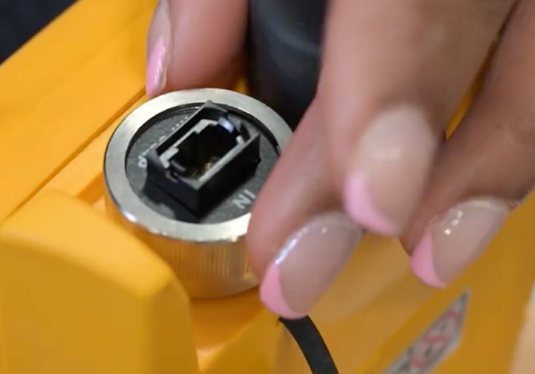
The CertiFiber Max stands apart from existing testers on the market with native support for pinned and unpinned 12-, 16, and 24-fiber MPOs, as well as 16- and 24-fiber MMC interfaces. This native support enables a true 1-jumper reference, providing the fastest and most accurate measurements for insertion loss and length. Using tool-free UniPort™ input adapters, technicians can quickly switch between these connector types in the field.
"As MMC deployments continue to expand rapidly, the CertiFiber Max tester plays a critical role in supporting a robust MMC ecosystem, delivering reliable testing for next-generation AI networks," said Stroup of US Conec.
Beyond accurate loss and length testing for a broad range of multi-fiber links, the Max tester simplifies complex multi-fiber polarity. It not only verifies the polarity for a specific polarity scheme and connector type during testing, but it also automatically determines and documents the polarity scheme. This intelligence is paired with the latest tester features, including integrated fiber inspection via the FI-3000 camera, Wi-Fi results uploading, and full support for LinkWare™ PC Cable Test Management Software, which enables managing the results from multiple testers and generating professional reports.
With multiple multi-fiber interfaces, CertiFiber Max has made setting the 1-jumper reference mistake-proof thanks to its Set Reference Wizard feature and unique, color-coded Y Test Reference Cords (TRCs). Based on the intuitive interface of the popular duplex CertiFiber Pro tester, this Wizard uses step-by-step color-coded animation to prevent incorrect referencing. It starts by providing the required inventory of adapters, TRCs, and verification cords for the chosen application. It then guides the user through setting the reference and verifying TRC performance, leveraging the color coding on the TRCs, ports, and display to reduce user mistakes. The Wizard automatically stores the reference values and TRC verification results and includes them in your test results.
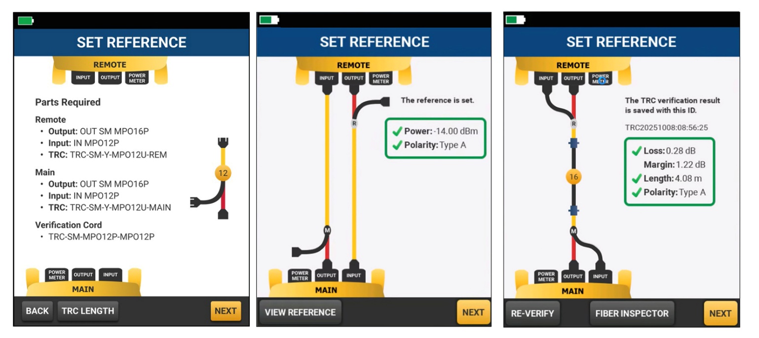
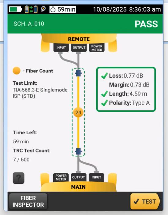
When the reference has been set and the TRCs are verified, CertiFiber Max is ready to test. Disconnect the TRCs from the verification cord (never from the tester) and connect them to the link under test. Engineered for speed, the Max tester completes a full test and saves results in just one second.
CertiFiber Max includes an optional feature that tracks the number of tests performed with a specific set of TRCs and the time since the reference was set. While Fluke Networks recommends TRC verification every 288 tests, users can set custom limits to ensure that contaminated or degraded TRCs never compromise a project's results. Tracking how long it has been since a reference was set can also be helpful. If a long time elapsed between when the reference was set and verified and when it is time to test, changes in temperature, time, or contamination may reduce the accuracy of field measurements. In that case, it is best to reinspect the TRC and reset the reference to minimize uncertainty.
Beyond testing: streamlining multi-fiber projects with LinkWare™ Live
While the CertiFiber Max takes multi-fiber testing to a new level, users can also streamline their certification projects through LinkWare Live. This cloud-based service increases efficiency, accuracy, and ease of documentation in certification testing, helping to boost integrator reputation and revenue.
- Remotely set up fiber testing parameters and cable IDs and download to any Max tester for mistake-free testing among technicians of all skill levels.
- Divide large projects into smaller subprojects and assign to teams or subcontractors for improved scheduling and streamlined testing.
- Upload and consolidate multiple test results from remote sites over Wi-Fi straight from the job site to minimize time wasted collecting and sorting test results.
- Integrate with LinkWare Cable Test Management Software to generate professional certification reports for customers.
- Gain real-time access to every certification project and drill down to individual test results for complete visibility to diagnose issues early, eliminating expensive rework.
- Track the last used location, monitor the status of every tester, and automate updates to ensure testers are always properly calibrated and running the latest firmware.
- Integrate with leading industry labeling solutions to quickly generate accurate labels from the LinkWare Live database.
Outpace complexity, scale with confidence
In a world where next-generation speeds and AI-driven data center architectures are the new baseline, there is no margin for error. The transition from manual, cumbersome duplex testing to the streamlined precision of multi-fiber MPO and MMC testing with the CertiFiber Max is more than just a technical upgrade — it is a commitment to the reliability of the high-performance, data-intensive applications driving the digital economy.
By combining advanced third-generation multi-fiber testing with the widely used Versiv test system and LinkWare cloud-integrated project management, data center professionals can finally outpace the growing complexity of high-density, multi-fiber links. In the race to scale, the right certification strategy with CertiFiber Max ensures that critical multi-fiber infrastructure delivers application assurance for scaling the modern data center.