CertiFiber™ Max Optical Loss Test Set
Product Highlights
Maximum fibers. Maximum efficiency. Maximum advantage.
高达24芯光纤,更高效率,更大优势。
- Maximum speed: Measure loss, length, and polarity of up to 24 fibers in one second.
- Maximum efficiency: CertiFiber Max is part of the modular Versiv™ / LinkWare™ cabling certification system, used by more technicians than any other certifier.
- Maximum flexibility: Field-replaceable UniPort™ adapters connect to existing (MPO, MMC), pinned and unpinned, and future connector/pin configurations — test 8-, 12-, 16- and 24-fiber cables, with 32-fiber cables to come.
- Maximum accuracy: Standards-preferred one-jumper reference provides the least uncertainty in fiber measurements. Tracks time since reference setting and count of tests for TRCs to ensure compliance with test processes.
- Maximum ROI: The Versiv / LinkWare ecosystem supports Tier I (OLTS) and Tier II (OTDR) fiber testing, inspection, and even copper certification.
- 高速度:在一秒内测试多达 24 芯光纤的损耗、长度和极性。
- 高效率:CertiFiber Max 是模块化 Versiv™ / LinkWare™ 布线认证系统的一部分,拥有比任何其他认证测试仪更多的技术人员用户。
- 高灵活性:现场可换的 UniPort™ 适配器可连接到现有(MPO、MMC)、有销和无销以及未来的连接器/引脚配置——测试 8、12、16 和 24 芯光缆,32 芯光缆即将推出。
- 高准确度:标准推荐的一跳线参考方法可为光纤测量提供最低不确定性。跟踪自参考设置以来的时间和 TRC 测试次数,以确保符合测试流程。
- 高投入产出:Versiv / LinkWare 生态系统支持 Tier I (OLTS) 和 Tier II (OTDR) 光纤测试、检查甚至铜缆认证。
Overview
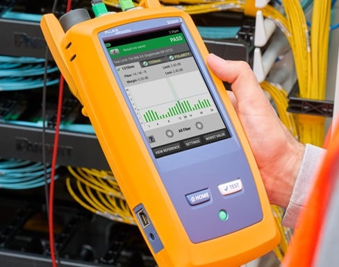
Maximize your multi-fiber certification efficiency with the CertiFiber™ Max OLTS. Measure loss, length, and polarity of up to 24 fibers in one second. Field-replaceable UniPort™ adapters connect directly to MPO, MMC, pinned and unpinned configurations, and more, giving you maximum flexibility. Set up your projects right the first time with the Versiv™ ProjX management system, or remotely with LinkWare™ Live. Minimize measurement uncertainty with 1-jumper reference setting and an integrated timer that tracks time since the reference was set and a counter for the number of times a Test Reference cord has been used. Troubleshoot fast with a built-in multi-fiber VFL, duplex power meter, and optional end face inspection.
And it’s all on the powerful, proven Versiv platform. With more than 10,000 Certified Cabling Test Technicians (CCTT) in the field, the CertiFiber Max OLTS is already part of a familiar, trusted tool set that’s built Fluke rugged, supported by Fluke expertise, and backed by gold-standard Fluke service and experience.
Features
UniPort™ Adapters for Connection to MPO 12/16/24 and MPO 16/24 Pinned and Unpinned Cables
The CertiFiber Max OLTS offers a native connection to MPO 12 pinned cables as standard and optionally supports MPO 12/16/24 and MMC 16/24 pinned or unpinned cables without complicated breakout cables or adjusting pin configurations. Changing configurations is as simple as swapping the field-changeable UniPort™ adapters and using the appropriate test reference cords. UniPort adapters allow connection of any MPO 12/16/24 and MMC 16/24 pinned or unpinned cable to the test port and provide protection for the test port. TRC cords are available to support these same configurations.
|
|
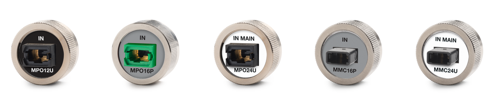
Field-interchangeable UniPort adapters allow direct connection to MPO 12/16/24 and MMC 16/24 pinned and unpinned cables
Designed for Maximum Accuracy
With decades of experience designing the world’s most accurate calibration equipment, we’ve built the CertiFiber Max OLTS to meet the exacting measurement requirements of today’s highest-performance fiber networks. But even the most accurate tester will deliver poor results unless it’s used properly. Manufacturers and standards recommend one-jumper reference setting for the most accurate measurements, and the CertiFiber Max OLTS offers that for every cable configuration.
To reduce errors in the field, the tester includes a “Wizard” that takes the technician step-by-step through the crucial referencing process. Mistakes made in reference setting can result in the loss of an entire day’s work. The Wizard specifies the exact accessories needed, monitors the user’s process through the steps, verifies whether measurements are within acceptable limits, allows cleaning of the end faces, and stores the critical reference values for reporting. UniPort adapters are color-coded to match the Wizard and Test Reference cords, which feature reference-quality fiber and connectors.
|
|
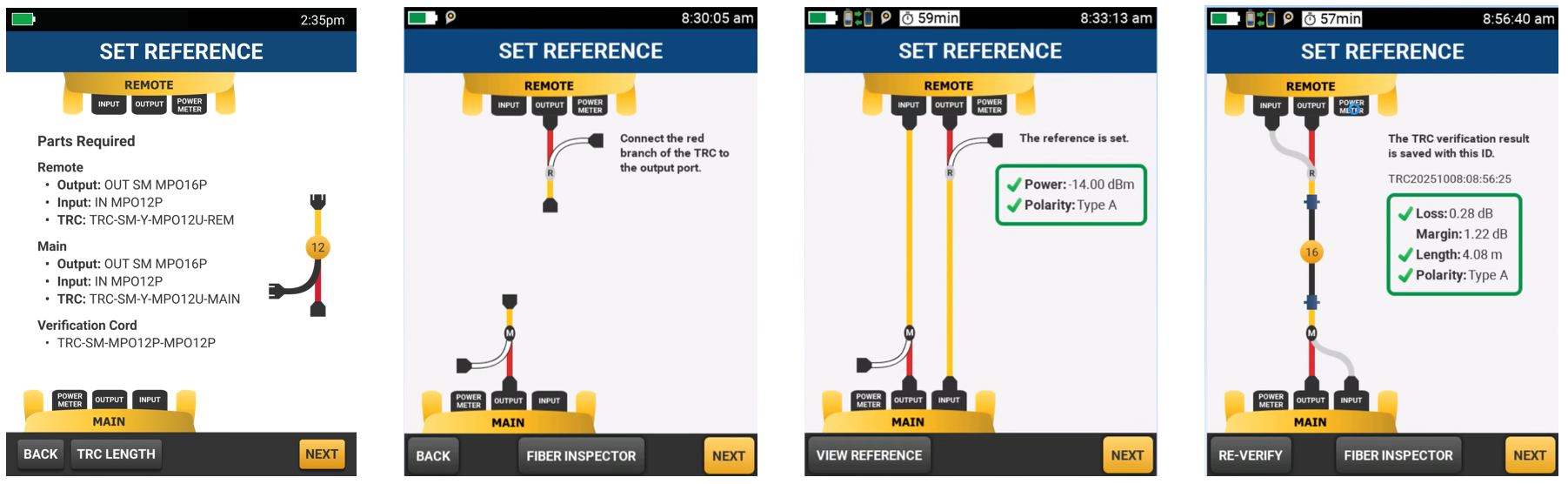
The Set Reference Wizard simplifies the setup process and greatly reduces errors. Left: List of all accessories required for the selected test are displayed. Middle left: The Wizard displays the steps and verifies that each has been performed. Middle right: The CertiFiber Max OLTS provides a 1-jumper reference setting for all MPO 12/16/24 and MMC 16/24 pinned and unpinned cables. Right: Reference values are checked for compliance and stored as proof of proper setting.
Results of the reference setting (including measured power and loss of the verification cords for each fiber tested) are stored and presented with project test reports, providing proof the process was done correctly.
Simple Results with Details
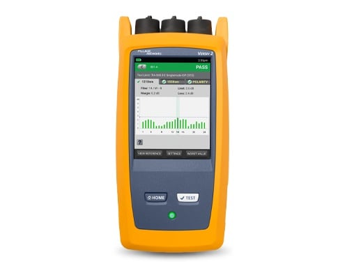
Designers can set limits using the built-in calculator — simply choose a standard, enter the number and type of connectors in the link, and the CertiFiber Max OLTS determines the length-based loss limits for the test. Or choose a specific application or enter custom limits based on the job specification. Either way, the technician sees a simple PASS or FAIL for each link tested, along with the worst-case loss margin, length, and polarity. Touching the screen shows loss on each fiber, and a polarity diagram.
|
|
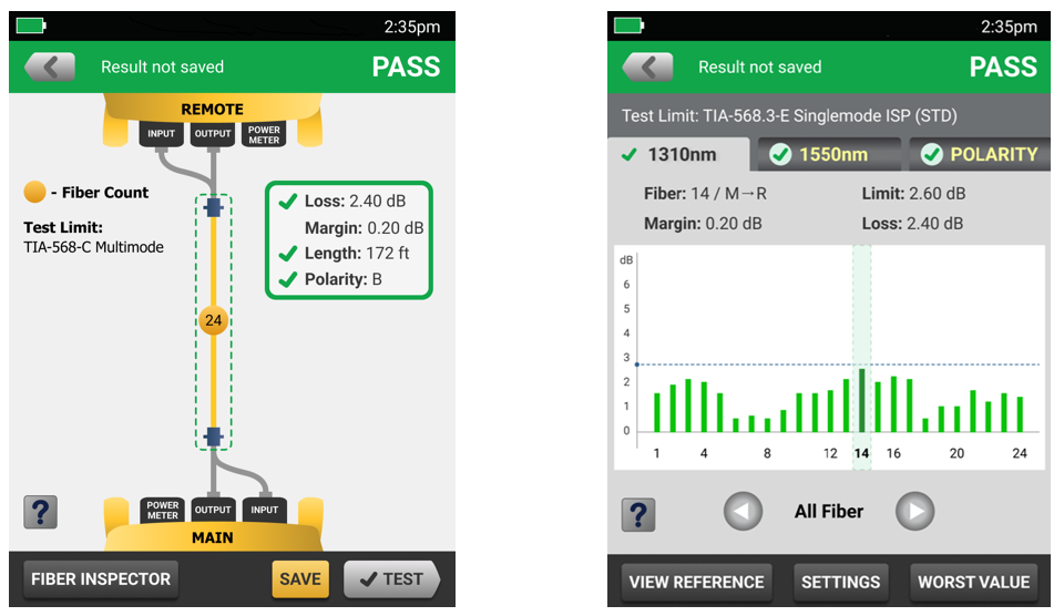
Left: Results screen indicates PASS or FAIL results and shows worst margin, length, polarity, number of fibers tested, and test limits. Touching the fiber under test (marked “24” in this case) brings up the detailed results by fiber (right) and wavelength along with polarity detail.
Efficiency and Ease of Use
In one second, the CertiFiber Max OLTS can test and store results for a cable with up to 24 fibers. But Versiv cuts the overhead around the test time as well. Its ProjX management system means that the tester can be set up ahead of time with only the cable types, limits, and identifiers for the job — which reduces confusion and mistakes. Versiv uses a tone to indicate when the far-end tester is connected and can be set up to start tests, save results, and increment to the next cable identifier automatically, saving even more time on large projects.
|
|
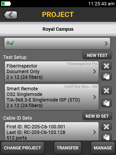
The Versiv ProjX management system shows the technician only the appropriate tests and cable identifiers for the job, reducing confusion and the chance for errors.
Counter and Timer
To maximize measurement certainty, some customers require limits on the length of time a specific reference setting can be used or how many measurements can be made with the same set of test reference cords. The CertiFiber Max OLTS includes an optional built-in timer that tracks how long it’s been since the reference was set, and the ability to set a limit so the user is warned before and after that time has been exceeded. In a similar fashion, an optional counter tracks how many tests have been performed with a specific set of TRCs, and limits can be set so that the user is warned when that limit is about to be and is exceeded.
|
|
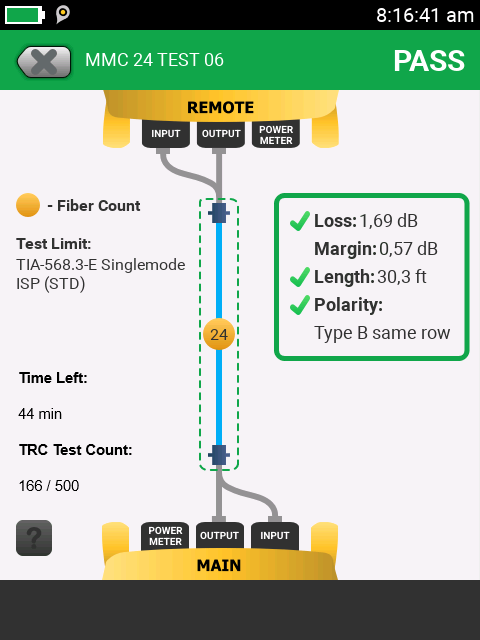
Results screen with optional timer and counter (lower left) displays time remaining since reference was set and number of tests performed with the current set of Test Reference Cords.
Integrated Visual Fault Locator and Duplex Power Meter
The CertiFiber Max OLTS is not only an efficient testing machine, but it can help troubleshoot as well. A Visual Fault Locator (VFL) can illuminate any fiber configuration up to 24 fibers simultaneously for troubleshooting. Integrated into the source port (in both the main and remote) so that the VFL can be turned on to troubleshoot the cable by techs at both ends, without disconnecting it, which speeds troubleshooting. A duplex power meter port with adapters for SC or LC connectors can be used to measure power from cassettes or duplex fibers.
Integrated Inspection
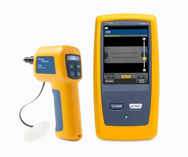
Fiber optic connector end-face contamination is a leading cause of fiber failures. Fiber loss testing can expose this problem, but dirty connections make fiber testing time consuming and inaccurate. Dirt can be an issue before, during, or after fiber optic certification testing, and can migrate from one fiber optic connector end-face to another upon mating, so both ends of any connection must always be inspected and cleaned if necessary.
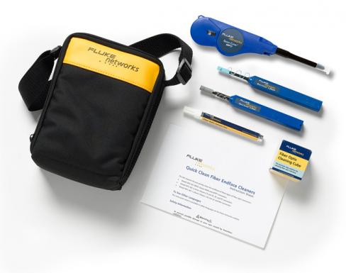
The CertiFiber Max OLTS provides double-ended fiber optic inspection capability through the use of two Versiv Main units along with two FI-3000 FiberInspector™ Ultra cameras. The double-ended fiber optic inspection capability allows inspection and automated PASS/FAIL results for MPO or MMC (as well as single-fiber) end faces at both ends of the fiber link in seconds. Store inspection images and PASS/FAIL results along with the loss, length, and polarity data in a single report. Fluke Networks also provides a wide array of tips for inspecting single fibers and cleaning supplies for multi-, duplex- and single fibers.
|
|
LinkWare Live
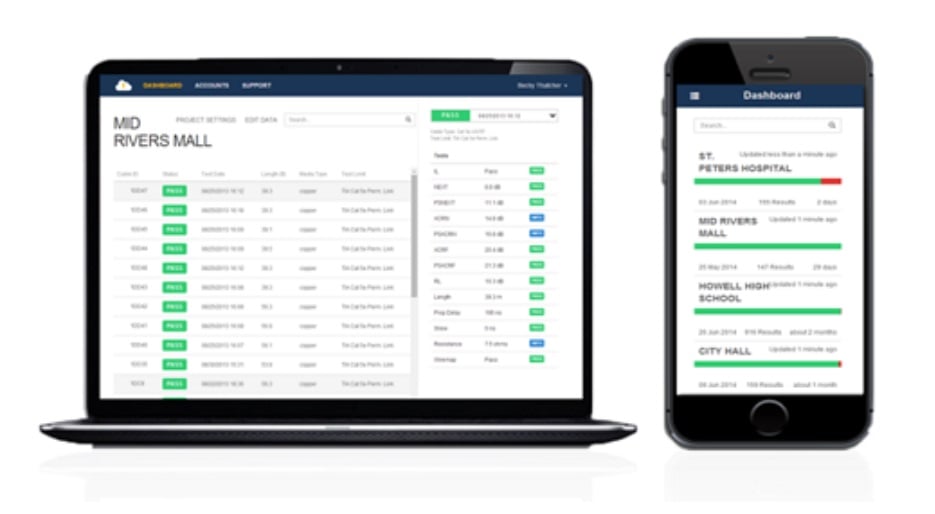
LinkWare™ Live is Software as a Service from Fluke Networks for cabling professionals managing multiple projects. It quickly, easily, and affordably provides unmatched job visibility and superior project control from anywhere, at any time.
LinkWare Live increases productivity because you don’t need to recall testers from the field just to download test results. Just upload the results from the tester to LinkWare Live from the jobsite so you can finish sooner, get home sooner, and get paid faster. LinkWare Live reduces reporting time by automatically consolidating all results into the correct job, and it cuts rework by reducing the chance of losing test results if something happens to the testers or memory cards. LinkWare Live provides instant access to results for faster troubleshooting and real time visibility into project status from any location. It fully integrates with LinkWare PC for fast reporting.
LinkWare Live also reduces errors by allowing project managers to set up testers remotely through smartphones, tablets, or PCs. Every aspect of the project, including cable types, limits, and cable identifiers, can be downloaded, eliminating the chance for operator error. And if someone changes that setup, LinkWare Live will let you know.
|
|
The CertiFiber Max OLTS connects to the LinkWare Live service via Wi-Fi or wired connections to provide remote setup, results uploading, and testing status information.
LinkWare PC Management Software
With LinkWare™ PC management software, CertiFiber Max users can easily access the ProjX management system data, generate reports, and upgrade the software in their testers. Project managers have full capabilities to monitor workflow and consolidate test results.
LinkWare PC provides automated statistical reports. That moves you above and beyond page-per-link reporting to see your entire cabling infrastructure in one summary. It analyzes and transforms test results into charts to reveal cabling plant performance. It even summarizes your entire cabling infrastructure in a compact, graphical format, so it's easy to verify margins and spot anomalies. Previous versions of LinkWare PC are backward compatible with new versions, so you can stay current and integrate tests from different testers into a single test report.
Combine the CertiFiber Max OLTS Tier 1 (loss, length, and polarity) and fiber inspection images in a single report while managing multiple jobs simultaneously. Add a company logo to give your report the finishing touch before offering it to your customer for system acceptance. The advantage of the system is that no matter which Fluke Networks cabling certification tester you use, LinkWare PC reports it all.
|
|
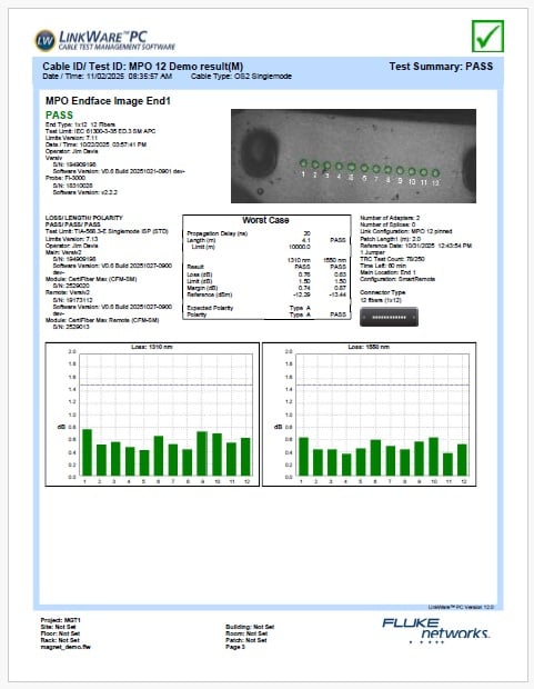
LinkWare PC report showing end face image and loss results (including PASS for each) for a 12-fiber MPO cable.
Models & Accessories
Models
CFM-100S GOLD
CFM-100S Gold Support
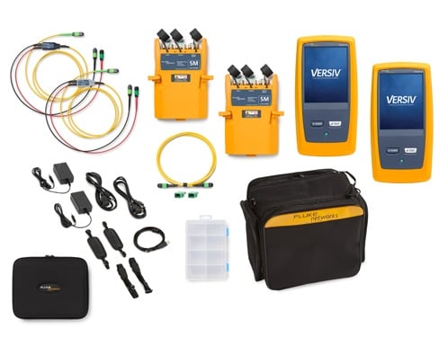
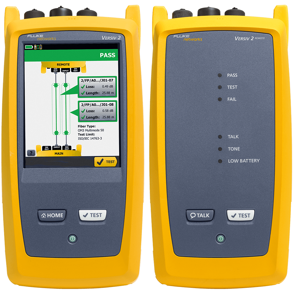
CertiFiber Max Single-mode OLTS Test Set with two Versiv Mains. Includes: 2 Versiv Main units including Wi-Fi, (2) HandStrap, (2) Shoulder Straps, USB Interface Cable, (2) AC Chargers; Two CertiFiber™ Max single-mode modules with MPO 12 pinned UniPort™ adapters, MPO 16 pinned output ports, LC input ports plus test reference cord with connectors for main unit source and meter ports and connection to cable under test; second test reference cord with connectors for remote unit source and meter ports and connection to cable under test, one verification cord and two MPO 12 couplers; Versiv-XL cube case, zippered Test Reference Cord case, UniPort case, safety card, Quick Reference Guide, warranty card and statement of calibration.See Photo
CFM-100S/GLD
CFM-100S CertiFiber Max Single-mode OLTS Test Set with two Versiv mains,1 yr Gold support.
CFM-100S-NW GOLD
CFM-100S-NW Gold Support
CertiFiber Max Single-mode OLTS Test Set with two Versiv mains, no Wi-Fi. Includes: 2 Versiv Main units without Wi-Fi, (2) HandStrap, (2) Shoulder Straps, USB Interface Cable, (2) AC Chargers; Two CertiFiber™ Max single-mode modules with MPO 12 pinned UniPort™ adapters, MPO 16 pinned output ports, LC input ports plus test reference cord with connectors for main unit source and meter ports and connection to cable under test; second test reference cord with connectors for remote unit source and meter ports and connection to cable under test, one verification cord and two MPO 12 couplers; Versiv-XL cube case, zippered Test Reference Cord case, UniPort case, safety card, Quick Reference Guide, warranty card and statement of calibration.See Photo
CFM-100S-NW/GLD
CFM-100S/NW CertiFiber Max Single-mode OLTS Test Set with two Versiv mains,1 yr Gold support, no Wi-Fi
CFM-100SI GOLD
CFM-100SI Gold Support
CertiFiber Max Single-mode OLTS Test Set with two Versiv mains, inspection cameras. Includes: 2 Versiv Main units including Wi-Fi, (2) HandStrap, (2) Shoulder Straps, USB Interface Cable, (2) AC Chargers; Two CertiFiber™ Max single-mode modules with MPO 12 pinned UniPort™ adapters, MPO 16 pinned output ports, LC input ports plus test reference cord with connectors for main unit source and meter ports and connection to cable under test; second test reference cord with connectors for remote unit source and meter ports and connection to cable under test, one verification cord and two MPO 12 couplers; two each FiberInspector ™ cameras, each with with keyless MPO 12-24 APC tip, Single Fiber Adapter for FI-1000 tips, AC charger, Getting Started Guide, Holster, box for tip storage; Versiv-XL cube case, zippered Test Reference Cord case, UniPort case, safety card, Quick Reference Guide, warranty card and statement of calibration.See Photo
CFM-100SI/GLD
CFM-100SI CertiFiber Max Single-mode OLTS Test Set with two Versiv mains, inspection cameras,1 yr Gold support
CFM-100SI-NW GOLD
CFM-100SI-NW Gold Support
CertiFiber Max Single-mode OLTS Test Set with two Versiv mains, inspection cameras, no Wi-Fi. Includes: 2 Versiv Main units without Wi-Fi, (2) HandStrap, (2) Shoulder Straps, USB Interface Cable, (2) AC Chargers; Two CertiFiber™ Max single-mode modules with MPO 12 pinned UniPort™ adapters, MPO 16 pinned output ports, LC input ports plus test reference cord with connectors for main unit source and meter ports and connection to cable under test; second test reference cord with connectors for remote unit source and meter ports and connection to cable under test, one verification cord and two MPO 12 couplers; two each FiberInspector ™ cameras, each with with keyless MPO 12-24 APC tip, Single Fiber Adapter for FI-1000 tips, AC charger, Getting Started Guide, Holster, box for tip storage; Versiv-XL cube case, zippered Test Reference Cord case, UniPort case, safety card, Quick Reference Guide, warranty card and statement of calibration.See Photo
CFM-100SI-NW/GLD
CFM-100SI-NW CertiFiber Max Single-mode OLTS Test Set with two Versiv mains, inspection cameras,1 yr Gold support, no Wi-Fi
CFM-S-ADD GOLD
CFM-S-ADD Gold Support
CertiFiber Max Single-mode Module set with MPO12 Test Reference Cords, no Versiv. Includes: Two CertiFiber™ Max single-mode modules with MPO 12 pinned UniPort™ adapters, MPO 16 pinned output ports, LC input ports plus test reference cord with connectors for main unit source and meter ports and connection to cable under test; second test reference cord with connectors for remote unit source and meter ports and connection to cable under test, one verification cord and two MPO 12 couplers, Versiv-XL carry case and zippered test reference cord case, safety card, Quick Reference Guide, warranty card and statement of calibration.See Photo
CFM-S-ADD/GLD
CertiFiber Max Single-mode Module set with MPO12 Test Reference Cords, no Versiv, 1 yr Gold support
CFM-S-MOD
CFM-S-MOD
CFM-EXPAND-S-MPO12
CFM-EXPAND-S-MPO12
CFM-EXPAND-S-MPO16
CFM-EXPAND-S-MPO16
CFM-EXPAND-S-MPO24
CFM-EXPAND-S-MPO24
CFM-EXPAND-S-MMC16
CFM-EXPAND-S-MMC16
CFM-EXPAND-S-MMC24
CFM-EXPAND-S-MMC24
CFM-TRC-S-MPO12U
CFM-TRC-S-MPO12U
CFM-TRC-S-MPO16U
CFM-TRC-S-MPO16U
CFM-TRC-S-MPO24U
CFM-TRC-S-MPO24U
CFM-TRC-S-MMC16U
CFM-TRC-S-MMC16U
CFM-TRC-S-MMC24U
CFM-TRC-S-MMC24U
CFM-TRC-S-MPO12P
CFM-TRC-S-MPO12P
CFM-TRC-S-MPO16P
CFM-TRC-S-MPO16P
CFM-TRC-S-MPO24P
CFM-TRC-S-MPO24P
CFM-TRC-S-MMC16P
CFM-TRC-S-MMC16P
CFM-TRC-S-MMC24P
CFM-TRC-S-MMC24P
NFA-MPO12P-KIT
NFA-MPO12P-KIT
NFA-MPO16P-KIT
NFA-MPO16P-KIT
NFA-MPO24P-KIT
NFA-MPO24P-KIT
NFA-MMC16P-KIT
NFA-MMC16P-KIT
NFA-MMC24P-KIT
NFA-MMC24P-KIT
NFA-MPO12U-KIT
NFA-MPO12U-KIT
NFA-MPO16U-KIT
NFA-MPO16U-KIT
NFA-MPO24U-KIT
NFA-MPO24U-KIT
NFA-MMC16U-KIT
NFA-MMC16U-KIT
NFA-MMC24U-KIT
NFA-MMC24U-KIT
NFA-MPO16P-SM-OUT
NFA-MPO16P-SM-OUT
NFA-CFM-LC
NFA-CFM-LC
NFA-CFM-SC
NFA-CFM-SC
TRC-SM-VERIFY-MPO12P
TRC-SM-VERIFY-MPO12P
TRC-SM-VERIFY-MPO16P
TRC-SM-VERIFY-MPO16P
TRC-SM-VERIFY-MPO24P
TRC-SM-VERIFY-MPO24P
TRC-SM-VERIFY-MMC16P
TRC-SM-VERIFY-MMC16P
TRC-SM-VERIFY-MMC24P
TRC-SM-VERIFY-MMC24P
TRC-SM-VERIFY-MPO12U
TRC-SM-VERIFY-MPO12U
TRC-SM-VERIFY-MPO16U
TRC-SM-VERIFY-MPO16U
TRC-SM-VERIFY-MPO24U
TRC-SM-VERIFY-MPO24U
TRC-SM-VERIFY-MMC16U
TRC-SM-VERIFY-MMC16U
TRC-SM-VERIFY-MMC24U
TRC-SM-VERIFY-MMC24U
ADP-MPO12/24-A
ADP-MPO12/24-A
ADP-MPO16/32-A
ADP-MPO16/32-A
ADP-MMC12TO32-1A
ADP-MMC12TO32-1A
Specifications
Multi-Fiber Optical Power Meter (per module)
| Specifications apply at 23°C, unless otherwise noted. | |
| Parameter | Single-mode |
| Included UniPort Adapter | Non-contact MPO 12-fiber pinned |
| Optional Uniport Adapters | MPO 12/16/24 and MMC 16/24 pinned or unpinned |
| Detector Type | 16 large core fibers coupled to 16 InGaAs photodiodes. |
| Supported Fiber Type | Single-mode 9/125 µm |
| Calibrated Wavelengths | 1310 nm, 1550 nm |
| Power Measurement Linearity 1 | ±0.10 dB |
| Power Measurement Repeatability 1,2 | ±0.02 dB |
| Power Measurement Reproducibility 1,3 | ±0.1 dB |
| Power Measurement Uniformity 4 | ± 0.1dB |
| Loss Measurement Budget 5 | 10 dB |
| Re-calibration Period | 1 year |
| 1. For the measurement range -10 dBm to -20 dBm. All photodiodes, over the measurement range. After a 5-minute warmup. | |
| 2. Maximum variation of power measurements when the measurement is repeated multiple times (i.e. 5 times) without disturbing the optical connector during 5 seconds at -12-dBm SM. | |
| 3. Maximum variation of power measurements when the measurement is repeated multiple times (i.e. 5 times) when the optical connector is disconnected and reconnected between repeated measurements at - 12-dBm SM. | |
| 4. Maximum variation between any one detector when compared to any of the other detectors, including the optical power meter duplex port at -20dBm SM. | |
| 5. Loss measurement budget specification provides flexibility within the power measurement range, for example, -10 dBm to -20 dBm for single-mode. | |
Multi-Fiber Optical Sources (per module)
| Specifications apply at 23°C, unless otherwise noted. | |
| Output port | MPO 16 pinned |
| Fiber Type | 9/125 µm |
| Central Wavelengths (nm) | 1310 ± 20, 1550 ± 20 |
| Emitter Type | Fabry-Perot laser |
| Spectral Width (nm) 1 | ≤5 (1310 nm and 1550 nm) |
| Output Power (dBm) Nominal | ≥ -12 dBm |
| Power Stability (dB) 2 | ± 0.10 |
| Launch Condition 3 | Not applicable |
| Length Measurement Range 4 | up to 25 km |
| Length Measurement Uncertainty | +/- 1 meter + 1% of length |
| 1. RMS for Fabry Perot lasers; FWHM for LEDs (typical). | |
| 2. At constant temperature, relative to power level after 15-minute warm up, compliant for 8 hours. | |
| 3. At 850 nm. Measured at the output of an encircled flux maintaining patch cord connected to the module’s output port. | |
| 4. Length measurement is round trip time delay the cable under test. | |
Multi-Fiber Visual Fault Indicator (Source Port)
| Connector | MPO 16, pinned (when testing, this port will be connected to a Test Reference Cord which is available in MPO 12/16/24 and MMC 16/24 pinned and unpinned). |
| Total Output Power | >-5 dBm <0 dBm, continuous wave, at the 9/125 µm patch cord for single-mode source |
| Operating Wavelength | 635 nm nominal |
| Output Modes | Continuous, pulsed blink frequency (2 Hz to 3 Hz) |
| Laser Safety | Class II CDRH |
Optical Power Meter - Duplex Port (per module)
| Specifications apply at 23°C, unless otherwise noted. | |
| Parameter | Single-mode |
| Input Connector | Cylindrical ferrule duplex connectors (only one ferrule is measured at a time) |
| Default Port Adapter | LC Duplex |
| Optional Port Adapters | SC Duplex |
| Detector Type | 1 mm InGaAs photodiode accommodates one fiber at a time |
| Supported Fiber Type | Single-mode 9/125 µm |
| Calibrated Wavelengths | 1310 nm, 1550 nm |
| Power Measurement Range | +5 dBm to -45 dBm |
| Power Measurement Uncertainty 1 | < ± 0.35 dB |
| Power Measurement Linearity 1,2 | ±0.10 dB |
| Power Measurement Repeatability 3 | ±0.02 dB |
| Power Measurement Reproducibility 4 | ±0.05 dB |
| Optical Connector Interface | Accepts simplex LC or SC non-angled (UPC) and (APC) end face |
| Re-calibration Period | 1 year |
| 1. Under the following conditions: a. For calibrated wavelengths. Power level 10 µW (-20 dBm), continuous wave (CW) for absolute power. b. Divergent beam, NA = 0.20 for 50/125 µm and NA = 0.14 for 9/125 µm c. Ambient temperature 23° ± 3 °C d. FC/UPC connector with ceramic ferrule e. After a 15-minute warm-up f. Traceable to SI g. Based on calibration and metrology requirements. | |
| 2.For the measurement range -5 dBm to -40 dBm. | |
| 3. Maximum variation of power measurements when the measurement is repeated multiple times (i.e. 5 times) without disturbing the optical connector during 5 seconds at -30dBm MM and -12dBm SM. | |
| 4.Maximum variation of power measurements when the measurement is repeated multiple times (i.e. 5 times) when the optical connector is disconnected and reconnected between repeated measurements at -30dBm MM and -12dBm SM. | |
Environmental Specifications (tested with module installed into Versiv mainframe)
| Operating Temperature | -10°C to +45°C |
| Storage Temperature | -10°C to +60°C |
| Operating Relative Humidity | 0 % to 95 % noncondensing, 0°C to 35°C 0 % to 70 %, 35°C to 45°C |
| Vibration | Random, 2 g, 5 Hz to 500 Hz |
| Shock | 1-meter drop test |
| Safety | IEC 61010-1 |
| Pollution Degree | 2 |
| Altitude | Operating: 4 km |
| Storage | 12 km |
| EMC | IEC 61326-1 |