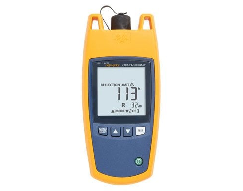
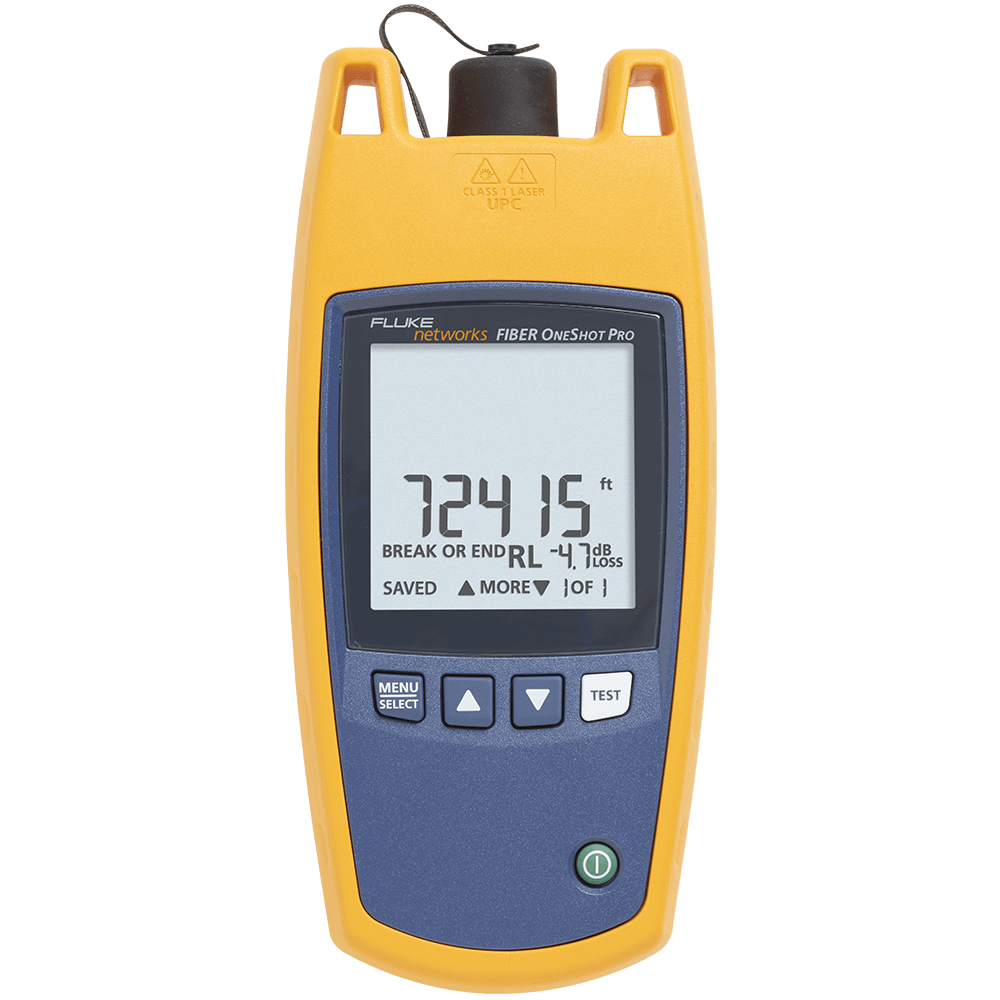
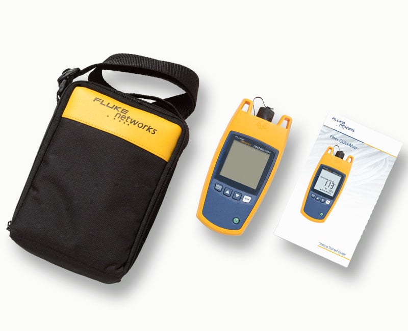
Fiber QuickMap™
Product Highlights
Multimode Fiber Distance and Fault Locator
- Works on multimode fiber, 50/125µm and 62.5/125 µm
- 850 nm output wavelength. Measure up to 4,921 feet (1,500 metres) of fiber in seconds
- Locate severe bends, high-loss splices, breaks and dirty connectors in multimode fiber
- Measure and locate high-loss splices
- Locate the end of a fiber
- Find potential sources of high bit error rates caused by reflectance from dirty or poor connections
- Detects live optical signals before it begins testing
- Quick set-up. Connect your fiber and press the Test button. No lengthy set-up necessary
- Find problems quickly. Six-second test time —no more blind troubleshooting that can waste hours
- Change the Index of Refraction (IOR) to improve fiber length accuracy
- Visible in dark areas. Backlighted display turns off automatically
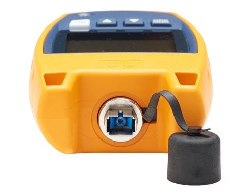
- Removable SC adapter is easily cleaned
- Optional LC, ST and FT interchangeable adapters are available
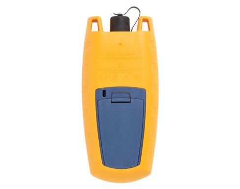
- Long battery life, 1,500 tests (typical) from 2 AA alkaline batteries
- Rugged construction; vibration and drop tested to 1 meter
Overview
VFLs work well for exposed lengths of fiber near a patch panel by illuminating bad connections and breaks. They are not very helpful for cable runs more than a few meters, or when the cable not visible or accessible, or when the laser light can’t penetrate the jacket.
Optical Time Domain Reflectometers (OTDR) provides graphical data and analysis along the entire length of a cable, way beyond the reach of a VFL, but they can be expensive and require more time to and skill to operate.
Fiber QuickMap fills the gap between a VFL and an OTDR. These models have the simplicity of a VFL, and provide distance and power information on high losses, breaks, and the end of the fiber. They also identify live fiber
Features
Locate Causes of Bit-Error Rates
While connector reflectance is a normal phenomenon in fiber cabling, too much of it can actually cause problems, especially within high bandwidth (10+ Gbps) systems. Excessive reflectance (usually caused by dirty end-faces or poor polishing) interferes with transmitter output, resulting in bit-error issues. Being able to locate and measure high reflective incidents helps to optimize network performance.
Locate the Most Common Causes of Multimode Fiber Failure
Discovering high loss incidents within a multimode channel is critical because they are the source of most enterprise fiber failures. These macrobends, contaminated, or damaged fiber end-faces that can create high loss are invisible to visual fault locaters, flashlights, and power meters. With a Fiber QuickMap, however, the user can quickly define loss thresholds to flag and locate any incidents of high loss.
Obtain Critical Visibility into the Multimode Channel
Having visibility into all the connection incidents within a channel is imperative because they are where most fiber failures in enterprise environments occur. The Fiber QuickMap troubleshooter will display the distances to multiple* connection incidents all the way until the end of (or break in) the link.
* A maximum of nine incidents can be displayedOne-Button Testing
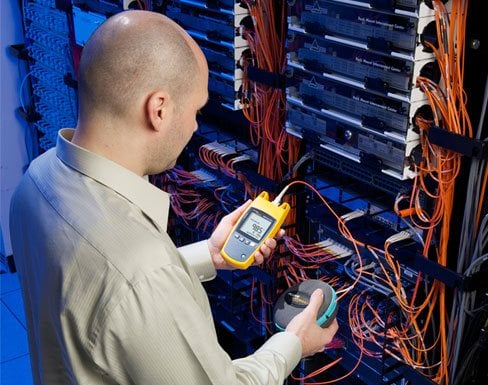
Fiber QuickMap can be used straight out of the box with no user-setup required. Simply turn it on, connect to the multimode link to be tested, and press the “TEST” button to obtain the channel visibility you need in order to quickly troubleshoot or verify connectivity. No need to fiddle with settings, fiber types, or standards.
Six-second Troubleshooting
The Fiber QuickMap troubleshooter, as a single-ended instrument, cuts down your troubleshooting time from hours to mere seconds. Averaging six seconds of test time, it quickly provides the visibility and data necessary to locate and fix any issues with your multimode fiber cabling. Tools normally used for troubleshooting are typically inefficient, ineffective, or both. Visual fault locators, lasers, or flashlights, while easy to use, have extremely limited troubleshooting capabilities because they are unable to distinguish or locate problematic loss or reflective incidents. They also require that the user maintain visual contact with the cabling while tracing its length to locate any faults. Not only is this process time-intensive, it is also unrealistic in many data center and campus environments in which the links run underneath floor tiles, behind walls, or underground. Power meters and sources are great for testing the entire channel to verify power and loss, but are inefficient for troubleshooting because the user must sequentially test a channel link-by-link, which can take several hours depending on the length of the channel and the number of links.
Models & Accessories
Models
FQM-M
FQM-M
FQM-100-M
FQM-100-M
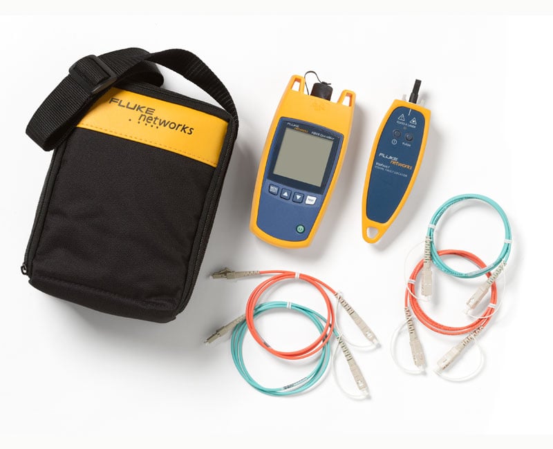
FQM-100-M-VFL
FQM-100-M-VFL
FQM-SFP-M
FQM-SFP-M
Accessories
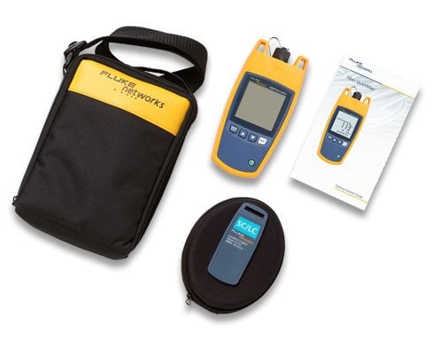
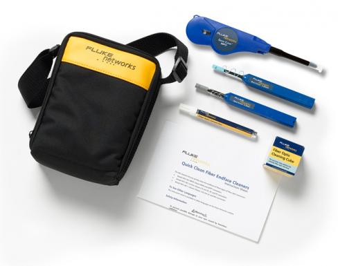
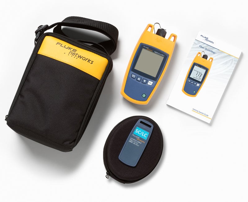
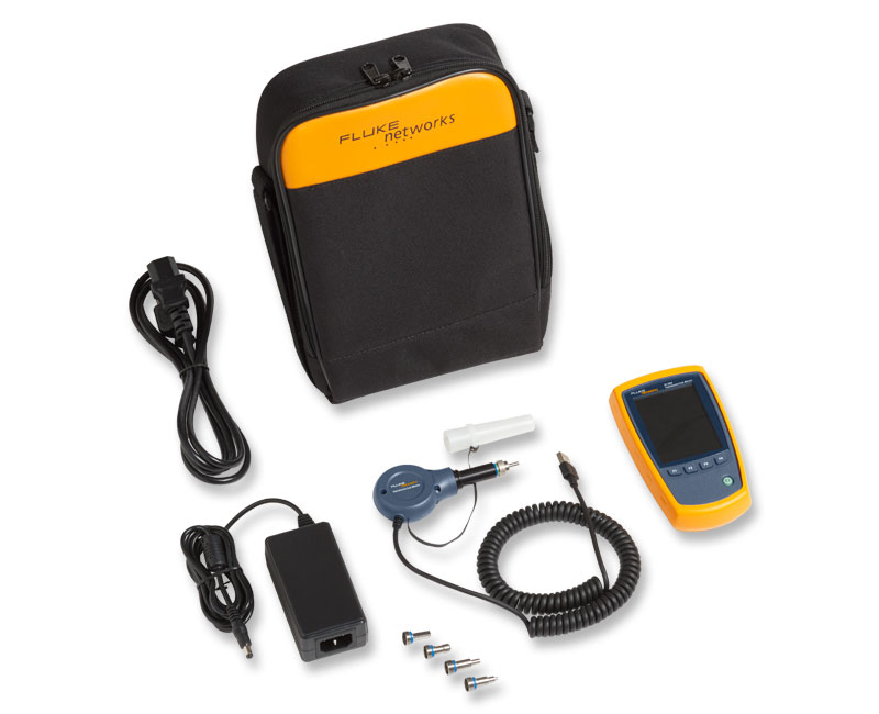
NFC-Kit-Box
NFC-Kit-Box
MMC-50-SCSC
MMC-50-SCSC
MMC-50-SCLC-M
MMC-50-SCLC-M
MMC-50-LCLC-M
MMC-50-LCLC-M
MMC-50-SCST
MMC-50-SCST
MMC-50-STST
MMC-50-STST
MMC-50-SCFC
MMC-50-SCFC
MMC-50-FCFC
MMC-50-FCFC
MMC-50-SCE2K
MMC-50-SCE2K
MMC-62-SCSC
MMC-62-SCSC
MMC-62-SCLC-M
MMC-62-SCLC-M
MMC-62.5-LCLC-M
MMC-62.5-LCLC-M
MMC-62-SCST
MMC-62-SCST
MMC-62.5-STST
MMC-62.5-STST
MMC-62-SCFC
MMC-62-SCFC
MMC-62.5-FCFC
MMC-62.5-FCFC
PA-SC
PA-SC
PA-LC
PA-LC
PA-FC
PA-FC
PA-ST
PA-ST
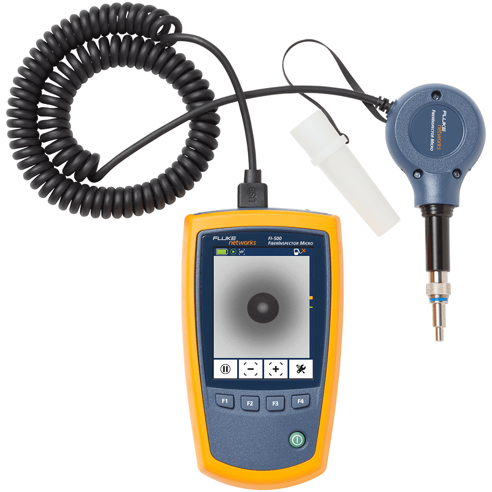
FI-500
FI-500
Specifications
Models
| Operating temperature with the battery | 0ºC to 50ºC |
| Non-operating temperature | -20ºC to 60ºC |
| Operating relative humidity (without condensation) | 95% (10ºC to 35ºC) 75% (35ºC to 40ºC) uncontrolled < 10ºC |
| Vibration | Random, 5 Hz to 500 Hz, MIL-PRF-28800F CLASS 2 |
| Shock | 1 meter drop test |
| Altitude | 3000m |
| EMC | EN 61326-1: 2004 |
| Certifications and compliance | Conforms to relevant European Union directives; Conforms to relevant Australian standards; Listed by the Canadian Standards Association CSA C22.2 No. 61010.1.04; Conforms to FCC Rules, Part A, Class A |
| Battery type | 2 AA alkaline batteries (no battery charger) |
| Battery life | 1500 tests (typical) |
| Laser safety | Class 1 CDRH Complies to EN 60825-2 |
| LCD type | Backlit black and white (segments) |
| Index of refraction range | 1.45 to 1.5 (factory default is 1.496) |
| Auto turn off | Automatically turns off after 5 minutes if no keys are pressed. Backlight turns off first. |
| Factory calibration interval | None |
| Output wavelengths | 850 nm ± 10 nm |
| Laser classification | Class 1 CDRH Complies to EN 60825-2 |
| Dynamic range | >11 dB |
| Maximum distance | 1500 meters or 4921 feet |
| Maximum number of incidents shown | 9 |
| Distance accuracy (0 m to 1500 m or 0 ft to 4921 ft) | ± (1 m + 0.1 % x length) for reflective incidents 1 ± (3 m + 0.1 % x length) for non-reflective incidents 2 |
| Testing speed | < 6 seconds typical |
| Connector | Removable/cleanable SC adapter, UPC polish |
| Fiber types tested | 50/125 µm or 62.5/125 µm multimode |
| Detection of reflective incidents 3 | -35 dB default threshold (User selectable: -20 dB to -45 dB in 5 dB increments) |
| Reflectance accuracy 4 | ± 4 dB |
| Maximum reflectance measurement | -20 dB |
| Detection of loss incidents 5 | 0.70 dB default threshold (user-configurable from 0.5 dB to 6.1 dB in 0.2 dB increments) |
| Bulkhead quality | If no fiber is attached or if the connector is dirty, the troubleshooter displays 0 m or 0 ft. |
| Live fiber detection | Detects optical signals from 600 nm to 1050 nm and shows ACTIVE LINE if a signal is there. Looks for a signal every 3 seconds after the first detec-tion. +7 dB maximum input power. |
Documents
Manuals
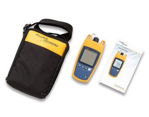
- FIBER QuickMap Users Manual, Rev. 3 User documentation
- Guida introduttiva del FIBER QuickMap (Italiano) Documentazione per l'utente
- FIBER QuickMap Getting Started Guide, Rev. 4 User documentation
Data Sheets
White Papers
Application Notes
- Fiber Testing Best Practices - Pocket Guide Request your 4” x 6”, sturdy pocket guide that is ideal to take on all your fiber jobs. Includes a quick-action summary and checklist, this guide is an invaluable tool to ensure you never miss a critical step during your fiber testing or troubleshooting.