During Tier 1 fiber testing, you must calibrate your tester to 0 dB to reference out the loss of any Test Reference Cords (TRCs). This is like placing a bowl on a scale and zeroing it to ensure the accurate weight of its contents. Let’s examine TRCs and why industry standards recommend the 1-jumper reference method for this crucial step.
What is a test reference cord?
Tier 1 testing, as defined by industry standards, measures the total insertion loss of a fiber link. This is done by using an optical loss test set (OLTS) with a light source at one end and a power meter at the other to measure the light exiting the opposite end. The loss measurement should include the loss of both the first and last connectors in the link, which reflects how the cabling plant will eventually be used.
Since it’s impossible to measure the loss of a single connector, connector loss is calculated as the loss of a mated pair. Therefore, measuring the loss of the first and last connectors in the link requires mating them to a similar, known-quality connector. This is where test reference cords (TRCs) come in.
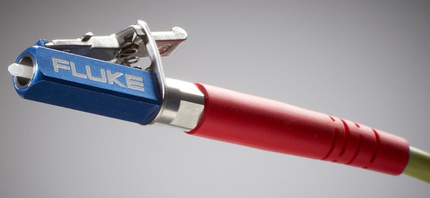
TRCs are explicitly used for certifying cabling systems. They are constructed of reference-grade cable and connectors with a very low loss — better than 0.1dB for multimode and 0.2dB for single-mode. This low loss is essential. Using a TRC with higher loss yields a pessimistic result, especially in links with low-loss connectivity, potentially causing a perfectly good link to fail and leading to costly, unnecessary reinstallation.
For testing multimode fiber links, TRCs must also be encircled flux (EF) compliant. EF is a metric that defines the required launch conditions on multimode fiber; it controls the light launch and strips out unwanted modes, minimizing uncertainty and inconsistencies caused by variations in different light sources. EF-compliant TRCs ensure that the EF-compliant source is maintained to the end of the cord where it connects to the link under test.
Proper TRC maintenance
As with any fiber-optic connector, the end face of the TRC connector can become contaminated with dust and debris. Dirty end faces on your TRC cause signal loss and reflections, leading to inaccurate, pessimistic test results. Dirty end faces can also contaminate the end faces of your test equipment and the fiber link under test.
Before testing, it is crucial to inspect, clean if necessary, and then reinspect TRC end faces, just as you would for any other connector in the link. Fluke Networks offers specialized tools for this task:
- FI-3000 FiberInspector™ Ultra Camera comes standard with tips for inspecting both UPC and APC 8-, 12-, and 24-fiber MPO end faces. Accessory tips are available for inspecting 16- and 32-fiber MPOs and very small form factor (VSFF) multi-fiber MMC connectors, as well as single fiber end faces.
- FI-7000 FiberInspector Pro is available with 1.25- and 2.5-mm universal tips for inspecting UPC and APC LC, FC, SC, and ST duplex connectors, as well as SN and MDC VSFF connectors.
TRCs wear out over time and need to be replaced. It’s best practice to verify TRC performance before testing; it’s the only way to ensure that any failed link isn’t due to a degraded TRC. Fluke Networks recommends verifying your TRCs every 288 tests and documenting those results. This establishes a benchmark for determining when a TRC is worn out and must be replaced. Fluke Networks Tier 1 certification testers feature a wizard to guide you through this verification process.
Some customers require you to track the total number of tests performed on a TRC and how long it’s been since a reference was set. If several hours have elapsed between the time the reference was set and when you’re ready to test, it’s best to reset the reference. The Fluke Networks CertiFiber™ Max OLTS includes an optional built-in timer and counter that tracks how long it’s been since the reference was set and how many tests have been performed with a specific set of TRCs; the tester warns you when you’re about to exceed those limits, ensuring you’re in compliance with your customer’s requirements.
Selecting the right test reference method
When testing, you must select the reference method: the 1-jumper, 2-jumper, or 3-jumper method. The 1-jumper reference method should be used whenever possible for testing fiber link loss, as it offers the least uncertainty.
- 1-jumper reference: This is the default method recommended by industry standards. It references out the TRC from the point where it connects to the light source on the tester to the point where it connects to the power meter at the far end. This correctly accounts for the loss of connections at both ends, which is why it offers the least uncertainty in the measurement.
- 2-jumper reference: This method references out the mated connection between the two jumpers, resulting in a final measurement that includes only one end connection. It is not recommended: it has the highest uncertainty of all reference methods and provides only a partial depiction of the total loss. It should be used only when one or both ends of the link are terminated with a plug.
- 3-jumper reference: This method references out two connector pairs and requires a more complex process, using a substitution cord to account for the losses of the first and last connector. It should only be used when the standard 1-jumper method is not feasible, such as when the connector type on your tester interface does not match the connector type of the link under test.
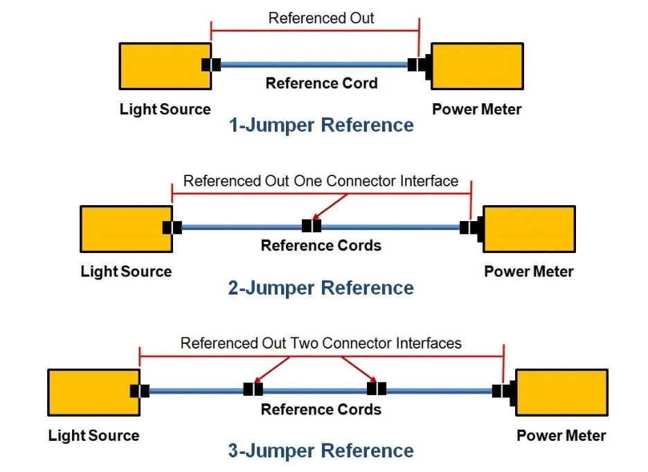
The 1-jumper reference provides the least uncertainty by accounting for the loss of both end connections. The 2- and 3-jumper methods offer less accuracy or incomplete loss measurements.
For new VSFF connectors like the CS, SN, and MDC, you might find that your OLTS lacks the required interface ports. To test in this scenario, you must use hybrid breakout cords and the more difficult, less accurate 3-jumper reference. Thankfully, Fluke Networks has two solutions that offer testing with the standards-preferred 1-jumper reference: The CertiFiber Pro is available with MDC VSFF adapters that accommodate the 1-jumper reference, and the CertiFiber Max includes a Set Reference Wizard that leads you step-by-step through the crucial 1-jumper referencing process.
Check out this video where our own Jim Davis demonstrates using the CertiFiber Pro to test a fiber link terminated to an MDC VSFF connector using the 1-jumper reference.
Simplified reference setting
Setting the reference is simple when you’re using Fluke Networks Versiv™ fiber certification testers. Versiv testers include a Set Reference Wizard that guides you through setup with clear, color-coded animations that match our TRCs. The Max tester even displays an inventory of the required adapters, test reference cords, and verification cords at the start of the process.
The Set Reference Wizard shows you precisely what to connect to the output ports of both the mainframe and remote units. It then steps you through connecting the units using the input ports. Once the tone and icon indicate that the two units are correctly connected, simply tap SET REFERENCE, and the reference is set in just a few seconds.
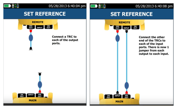
The Fluke Networks Set Reference Wizard uses clear, color-coded animations to step users through the process of setting a reference.
After the reference has been set, the Wizard guides you through the process of disconnecting the input ports — but never disconnect the TRCs from the output ports, or you’ll invalidate the reference and have to start over. The Wizard then steps you through verifying the TRCs. Once verified, you’re ready to begin testing. The Wizard automatically stores the reference values and TRC verification results and includes them in your test results.