To support higher cable density in data centers, very small form factor (VSFF) duplex fiber connectors are gaining ground. Some test devices support these newer interfaces; those that don’t present some challenges for Tier 1 testing and a shift from the recommended 1-jumper reference method. Let’s take a closer look at these connectors and the best practices for testing them.
CS and SN connectors
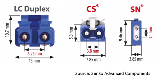
Introduced by Senko in 2018, the CS duplex fiber connector was designed primarily to fit two CS connectors in a QSFP-DD transceiver module. It offers better insertion loss and return loss performance compared to traditional LC connectors, and it does so in a reduced footprint. Featuring a 1.25mm ferrule, the CS connector is 40% smaller than the LC — the two fibers are spaced at just 3.8mm in a 7.85mm housing, compared to the LC that spaces the two fibers at 6.25mm in a 13mm housing.
And just in case the CS wasn’t small enough, Senko later introduced the SN duplex fiber connector, which spaces the two fibers vertically just 3.1mm apart in a 3.85mm housing. The SN connector is 70% smaller than the LC, allowing for four connectors in one QSFP-DD transceiver module to support breakout applications without the need for fan-out cables or cassettes.
Both CS and SN connectors feature a push-pull tab available in various lengths for easy access in ultra-high-density patching environments. Unlike LC connectors, which require space for vertical stacking due to their latch, these connectors can be closely stacked vertically to further enhance density. Both connectors also offer quick polarity reversal.
MDC connectors
To compete with the SN, US Conec introduced their version of a VSFF duplex connector: the MDC (Mini Duplex Connector). Slightly smaller than the SN, the MDC also uses the proven 1.25mm ferrule with vertically positioned fibers.
Like the SN, the MDC features a push-pull tab and quick polarity reversal. However, the MDC and SN connectors are not compatible — don’t try plugging one into the other’s transceiver interface or patch panel port.
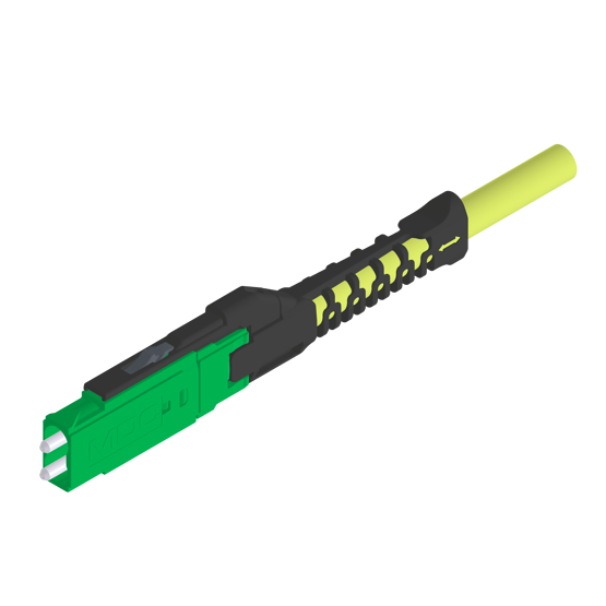
MDC duplex connectors by US Conec are slightly smaller than the SN connector.
VSFF duplex connector applications
CS connectors are primarily used to optimize wavelength density in single-mode coarse wave division multiplexing (CWDM) applications. A single LC duplex in a QSFP-DD transceiver requires 8 wavelengths per fiber to reach 800 Gig, which increases transceiver costs. In contrast, two duplex CS connectors (called a Twin CS) in a QSFP-DD transceiver support 4 wavelengths per fiber, significantly reducing transceiver costs within the same space.
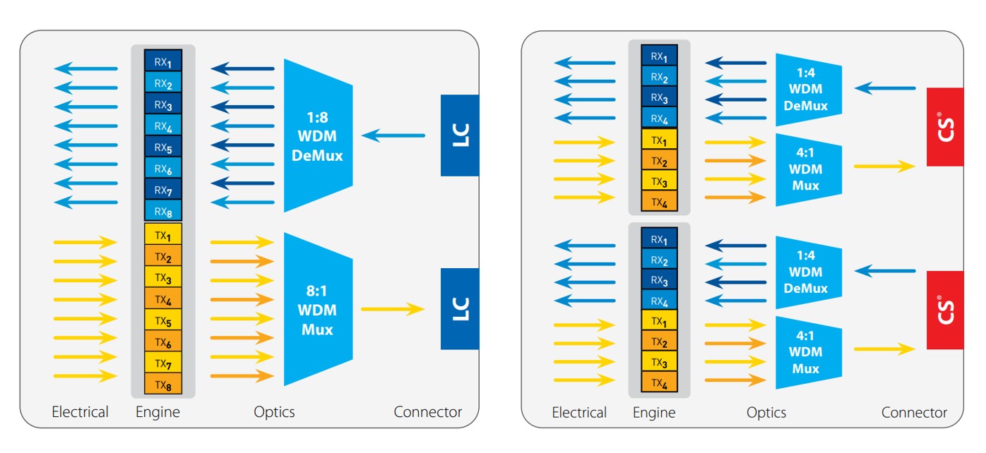
Two VSFF CS duplex connectors fit into a QSFP-DD transceiver to reduce the number of wavelengths and costs. Source: Senko
SN and MDC connectors are primarily used in breakout configurations, where a single switch port connects to multiple lower-speed switches or servers. By fitting 4 VSFF SN or MDC connectors in a QSFP-DD transceiver module, they support direct 4x100 Gig applications without the need for MPO-to-LC breakout cables or cassettes. In structured cabling environments, SN and MDC connectors offer triple the patch panel density of LC connectors, optimizing rack space utilization.
How to test CS, SN, and MDC connectors
Senko and UC Conec license the CS, SN, and MDC connectors, so you might see them offered by your cable and connectivity manufacturer. Because the connectors are new, you might also find that your light source and power meter (LSPM) or optical loss test set (OLTS) doesn't have CS, SN, or MDC interface ports.
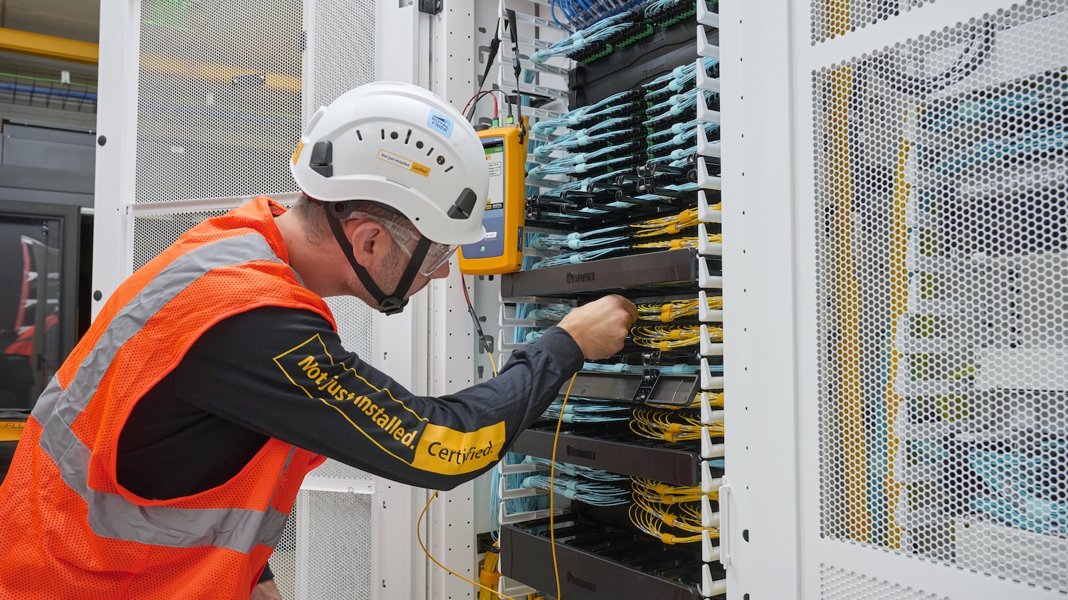
An LSPM like the Fluke Networks SimpliFiber™ Pro, which tests individual fibers using a single port, requires a CS, SN, or MDC to LC breakout cord on either side of the permanent link under test. In this scenario, each fiber needs to be tested for attenuation, so the light source and power meter must be moved from one fiber to the next at both ends. It’s important to note that since the launch cord must be disconnected from the LSPM, another reference measurement must be made before connecting to the second fiber.
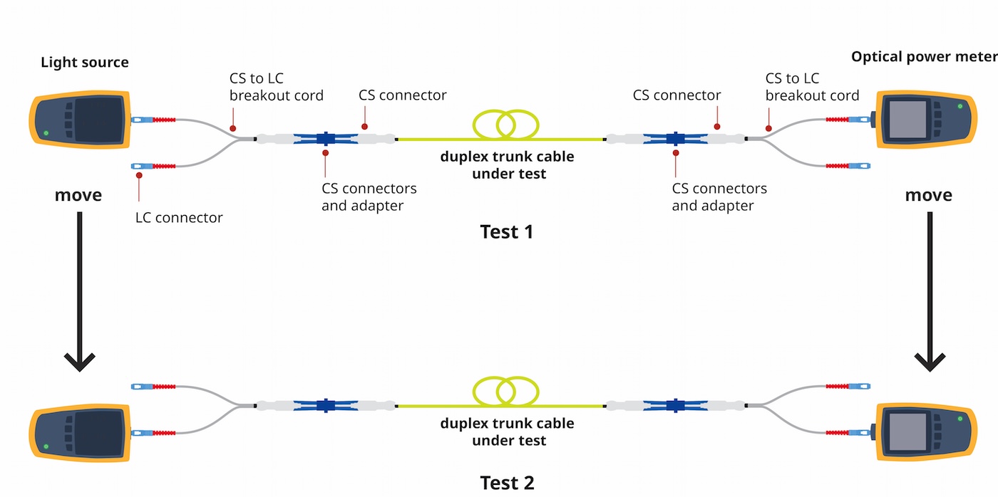
Testing CS-terminated cabling using an LSPM
If you're using an OLTS like the Fluke Networks CertiFiber™ Pro, designed for duplex testing (which significantly reduces test time and is the recommended tester for duplex systems), you don’t need a breakout cord when testing MDC connectors. That’s because the CertiFiber Pro is now available with MDC VSFF adapters and test reference cords (TRCs) to accommodate testing with a 1-jumper reference. In this video, our own Jim Davis uses the CertiFiber Pro to test a fiber link terminated to an MDC VSFF connector using a 1-jumper reference.
| How to test an MDC connector with a Fluke Networks CertiFiber™ Pro |
However, if you need to test a CS or SN connector, you still need a breakout cord. In this scenario, both LC connectors on the breakout cord are connected to the OLTS, eliminating the need to move the tester. With an OLTS, it's necessary only to test in the direction of transmission. So, in this scenario, only one test and one reference measurement are needed.

Testing CS-terminated cabling using an OLTS
The atypical 3-jumper method
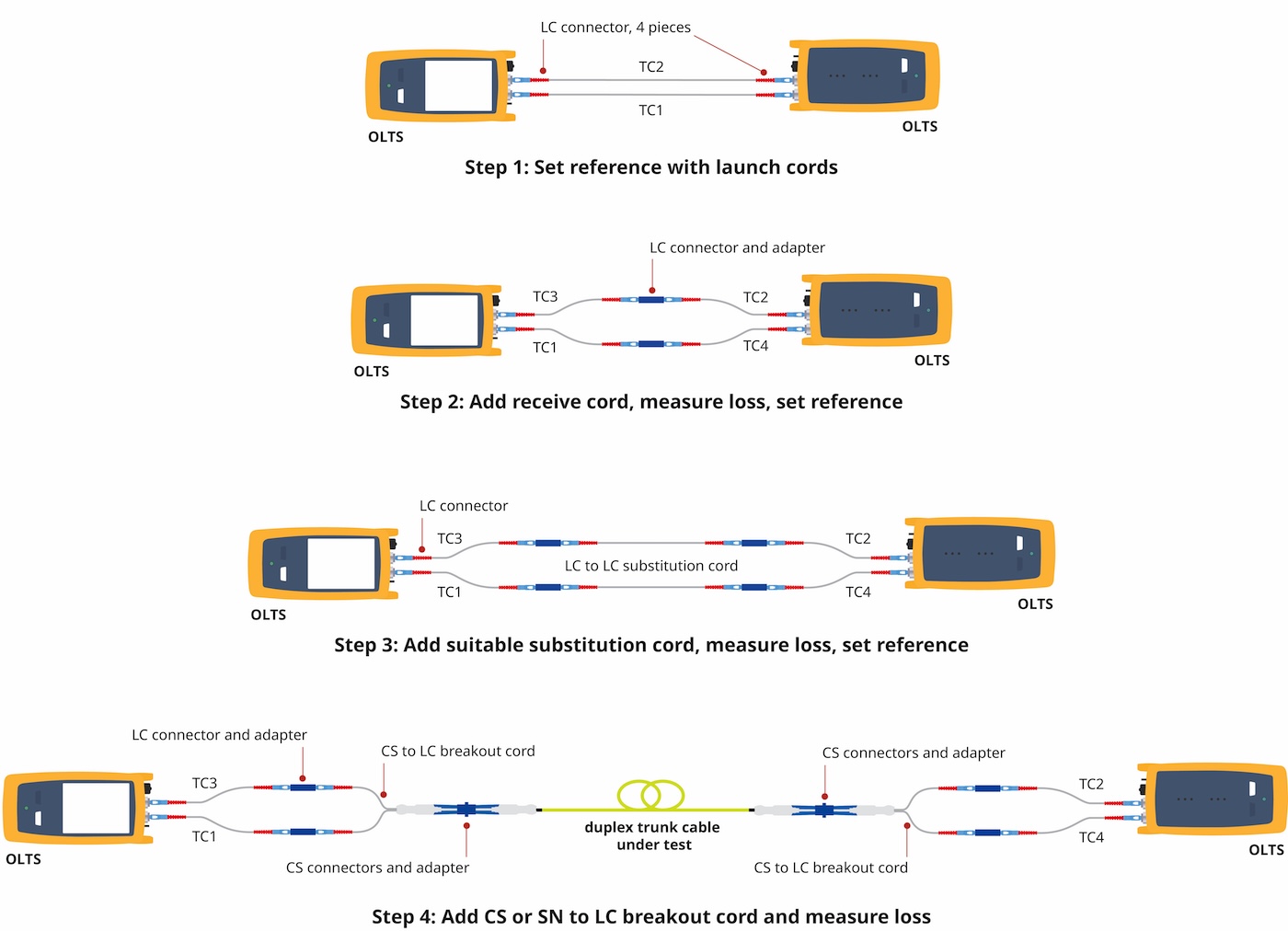
While the CertiFiber Pro with available MDC adapters and TRCs supports the recommended 1-jumper method for setting the reference, testing cabling with CS or SN connectors using breakout cords still requires a 3-jumper reference method.
- First, set a reference with LC launch cords (TC1 and TC2) to verify the condition of the end face connections.
- Next, disconnect the cords from the power meters (not the source), add the receive cords (TC3 and TC4), couple the launch cords to the receive cords (TC1 to TC4 and TC2 to TC3) using an LC adapter, and make a measurement to verify low loss, less than 0.25 dB, for each pair. Then, set the reference to 0 dB.
- The third step, once the reference has been set, is to insert a suitable duplex 2-meter substitution cord. This substitution cord should be inspected, cleaned, and verified for low loss before connecting — a cord with high loss could result in the cabling under test appearing to have a negative loss (e.g., gainer). With the substitution cord connected, you can reset the reference.
- Finally, replace the substitution cord with the CS or SN to LC breakout cord and attach the CS or SN connector to the cabling under test. Then measure the results. The measurement includes the loss of the fiber plus the loss of the two CS or SN connectors, minus the loss of the reference cords and LC connectors.