
As data center networks reach transmission speeds of 800 Gig and beyond, the evolution from NRZ (Non-Return-to-Zero) to PAM4 (Pulse Amplitude Modulation with 4 Levels) is reshaping fiber infrastructure requirements. Let’s examine how these signaling advancements affect the number of lanes and fibers in today’s applications and their implications for inspection and testing.

What is NRZ?
Every Ethernet link has network transceivers at each end that send and receive signals. These transceivers use signaling methods to translate digital data into the electrical or optical signals required for communication across network cabling. While fiber optic cable hasn’t changed much — OS2 single-mode fiber debuted in 2000 and OM4 multimode fiber in 2009 — signaling methods certainly have.
Non-return-to-zero (NRZ) signaling, which has been around since the early days of digital communications, became the standard signaling method for Ethernet in the 1980s. NRZ uses an encoding scheme with two signal levels that each represent a single bit: 1 and 0. The signal remains constant between consecutive bits of the same value, meaning it does not return to a neutral or zero state.
NRZ is a simple, cost-effective encoding scheme that uses less power due to fewer signal transitions. Over time, the baud rate (the number of signal transitions per second) has increased, allowing Ethernet lane rates to increase from 1 Gbps to 10 Gbps and now 25 Gbps with NRZ signaling.
But NRZ reaches a practical limit at 25 Gbps per lane. The high baud rate required to achieve faster lane rates makes the signal more vulnerable to noise and overlapping pulses. Although NRZ is still widely deployed for applications below 100 Gig, the demand for faster lane rates to meet the growing need for bandwidth called for a new encoding scheme.
What is PAM4?
Introduced around 2015, four-level pulse amplitude modulation (PAM4) signaling technology doubled the data rate of NRZ. It uses four signal levels that each represent two bits: 00, 01, 11, and 10. This allowed PAM4 signaling to support a 50 Gbps Ethernet lane rate, compared to 25 Gbps for NRZ at the same baud rate.
However, with more closely spaced signal levels, PAM4 is more susceptible to noise, including that caused by reflections. This requires more complex, power-hungry transceivers that rely on forward error correction (FEC), a method that encodes data with redundant information to detect and correct transmission.
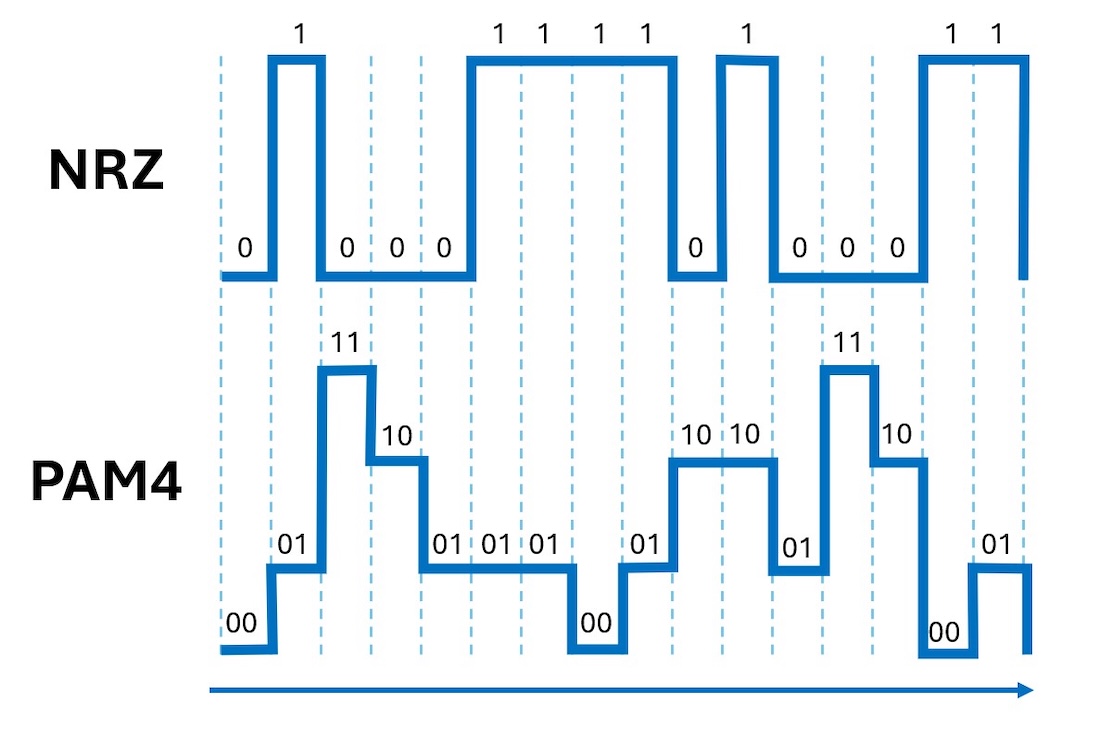
NRZ encoding uses two signal levels, representing 1 and 0. PAM4 uses four signal levels, representing 00, 01, 11, and 10, essentially doubling the data rate.
Why PAM4 is replacing NRZ: doubling lane rates
The PAM4-enabled 50 Gbps lane rate was a significant industry milestone. It led to the ratification of the IEEE 802.3cd in 2018 and IEEE 802.3cm in 2020, which defined standards for:
- 50 Gig Ethernet over 1 lane
- 100 Gig Ethernet over 2 lanes
- 200 Gig Ethernet over 4 lanes
- 400 Gig Ethernet over 8 lanes
Advances in digital signal processing (DSP) technology made it possible to correct for noise, dispersion, and other signal distortions. These developments enabled the doubling of the PAM4 baud rate, supporting a 100 Gbps single lane rate — which became the foundation for supporting 200 Gig over 2 lanes, 400 Gig over 4 lanes, and 800 Gig over 8 lanes.
Now, further advances in DSP have doubled the baud rate of PAM4 again, achieving a 200 Gbps lane rate. The upcoming IEEE 802.3dj, expected by mid-2026, will leverage this technology to support 800 Gig over just 4 lanes and 1.6 Terabit over 8 lanes. This is a significant improvement from the early days when a 10 Gbps NRZ-based lane rate required 10 lanes to support 100 Gig. Efforts are already underway to double the baud rate of PAM4 again, achieving a 400 Gbps lane rate. Each increase in signaling lane rate makes it possible to support faster application speeds with fewer lanes.
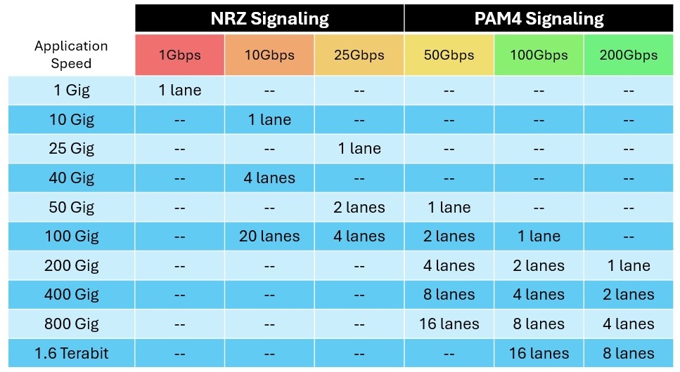
Increasing signaling lane rate supports faster application speeds over fewer lanes.
How signaling lanes impact fiber connectivity
Signaling lanes transmit data over optical fiber using wavelengths. Parallel optics technology achieves higher speeds by transferring data simultaneously across multiple fibers, typically using a single wavelength per fiber. Wavelength division multiplexing (WDM) technology achieves higher speeds by transferring data simultaneously across multiple wavelengths on a single fiber. This means a 4-lane, 400 Gig application can be achieved over 8 multimode fibers using parallel optics or 2 single-mode fibers using WDM.
- A 4-lane 400GBASE-SR4 multimode parallel optics application uses 4 fibers to transmit and 4 fibers to receive at 100 Gbps, all on the 850 nm wavelength.
- A 4-lane 400GBASE-LF4 WDM single-mode application uses 1 fiber to transmit and 1 to receive, with each fiber carrying four 100 Gbps signals on the 1271 nm, 1291 nm, 1311 nm, and 1331 nm wavelengths.
The lane rate, number of lanes, and the number of fibers determine connectivity for fiber optic applications. Parallel optics applications require multi-fiber connectors such as MPO/MTP, MMC, or SN-MT connectors — 4-lane applications typically use an 8-fiber connector, while 8-lane applications use a 16-fiber connector.
In contrast, WDM applications typically use duplex connectors, since they use multiple wavelengths on a single fiber pair.
It’s also possible to combine parallel optics and WDM technologies to reduce the number of fibers. For example, the 8-lane 400GBASE-SR4.2 multimode application, ratified in 2020, uses a 50 Gbps lane rate with 2 WDM wavelengths (850 nm and 910 nm) on each fiber. This approach allows data centers to upgrade from 100 to 400 Gig using their existing 8-fiber connectivity instead of upgrading to 16-fiber connectivity.
Inspection and cleaning considerations
PAM4 enables higher speeds but reduces signal margin, making fiber cleanliness and connector quality critical to performance. When inspecting connectors, it’s essential to use an inspection tool with a tip that matches the connector type and end face.
- Duplex connectors can be LC, SC, ST, and FC connectors. There are also very small form factor (VSFF) duplex connectors, including the MDC, CS, and SN. These newer, smaller connectors save space in ultra-high-density environments.
- MPO connectors can be traditional styles (8-fiber, 12-fiber, 24-fiber, 16-fiber, or 32-fiber) or newer VSFF multi-fiber connectors, like the increasingly popular MMC from US Conec (available in 12-, 16-, and 24-fiber versions) and the SN-MT from Senko (available in a 16-fiber version).
There are also two types of fiber end faces: ultra physical contact (UPC) and angled physical contact (APC).
- UPC end faces are flat, while APC end faces feature an 8-degree angle that reduces reflections in the fiber core.
- Single-mode duplex connectors can be either APC or UPC, whereas multimode duplex connectors are typically UPC. Single-ferrule duplex connectors yield a better polish than multi-fiber connectors, delivering good reflectance without the APC end face required by multi-fiber single-mode connectors.
- Single-mode MPO connectors use APC end faces, while multimode MPO connectors can be either APC or UPC.
- APC multimode MPO connectors are becoming more common for high-speed 400 Gig and 800 Gig applications, because PAM4 becomes even more sensitive to reflection at 100 and 200 Gbps lane rates.
For efficient inspections, the Fluke Networks FI-7000 FiberInspector™ Pro can inspect any APC or UPC duplex connector, providing automated PASS/FAIL results based on the IEC61300-3-35 cleanliness criteria. The FI-3000 FiberInspector™ Ultra Camera, also by Fluke Networks, offers automated PASS/FAIL inspection for single and multi-fiber UPC and APC multi-fiber connectors, including 12-, 16-, 24-, and 32-fiber MPOs and VSFF MMCs.
If, after inspection, connectors need to be cleaned, Fluke Networks Quick Clean™ cleaners come in a wide range of duplex and multi-fiber connector types, including VSFF duplex MDC and multi-fiber MMC. Unlike traditional swab cleaners that rely on the user’s technique, easy-to-use Quick Clean cleaners use a simple pushing motion with an audible click that provides consistent cleaning every time.
Certification testing best practices for fiber links
Certification testing to ensure fiber links meet the length, loss budget, and polarity requirements of the design specification requires knowledge of the specific application and connectivity type.
For the most accurate measurements, your certification tester’s onboard input connector and test reference cords (TRCs) must match the link under test. This allows for a 1-jumper reference, which offers the least measurement uncertainty. If they do not match, you may need to use the less accurate 3-jumper reference with a hybrid TRC on either side of the cabling under test.
For duplex links, the Fluke Networks CertiFiber™ Pro Optical Loss Test Set is available with various adapters and TRCs for testing LC, SC, ST, and FC duplex APC/UPC connectors, as well as new MDC VSFF connectors, with a 1-jumper reference. For multi-fiber links, the Fluke Networks CertiFiber MAX Optical Loss Test Set is available with various adapters and TRCs for testing pinned and unpinned MPO-12, MPO-16, and MPO-24 connectivity, as well as 16- and 24-fiber MMCs, with a 1-jumper reference. The MultiFiber™ Pro MPO tester also features an on-board MPO connector, with various adapters and TRCs for testing different fiber counts and APC/UPC end faces with a 1-jumper reference.
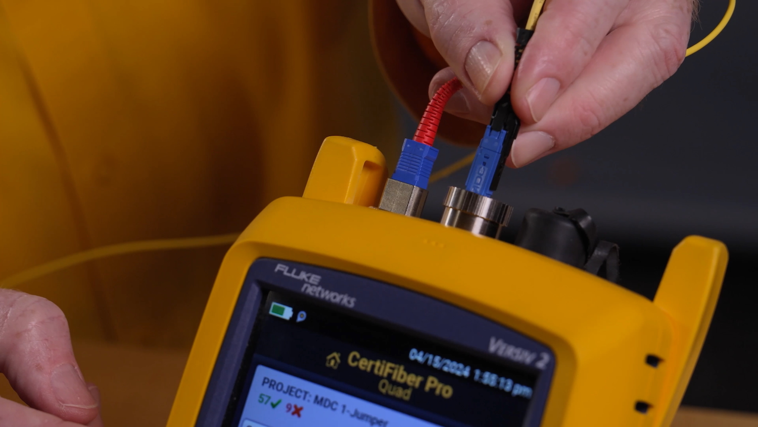
The Fluke Networks CertiFiber™ Pro Optical Loss Test Set is available with various adapters and TRCs, including new MDC VSFF connectors, enabling a 1-jumper reference
When testing WDM applications, it’s vital to test at both the shortest and longest wavelengths to cover the entire wavelength range. Shorter wavelengths are more sensitive to alignment problems (loss events), and longer wavelengths are more sensitive to issues caused by bends or cracks in the fiber. Comparing the loss values at both wavelengths can indicate a bend or crack if the loss is higher at the longer wavelength.
For single-mode WDM applications, testing at 1310 nm and 1550 nm wavelengths with the CertiFiber Pro is typically sufficient. CertiFiber Pro can also test at the 1490 nm and 1625 nm wavelengths for single-mode passive optical networks that use these higher wavelengths.
For multimode WDM applications in the 850 nm to 950 nm range, proper encircled flux testing with the CertiFiber Pro or MultiFiber Pro at 850 nm and 1300 nm provides comprehensive testing coverage.
Keep learning
- Is your fiber tester ready for 800G and beyond?
- Why the 1-jumper reference is recommended for accurate fiber optic testing
- MPOs in the data center and how to test them
- Tier 1 fiber testing best practices for duplex VSFF connectors
- New solutions for VSFF applications
- What you should know about VSFF connectors
- Easier fiber end face inspections: key changes to IEC 61300-3-35
- Fiber Optic Testers